Coding of concentric information

a technology of concentric information and coding method, which is applied in the field of coding a ring-shaped element of a digital image, can solve the problem of requiring many calculations during the filtering process

Active Publication Date: 2006-04-18
STMICROELECTRONICS SRL
View PDF4 Cites 25 Cited by
  • Summary
  • Abstract
  • Description
  • Claims
  • Application Information

AI Technical Summary

Benefits of technology

[0018]The present invention aims at providing a method for coding information wit...

Problems solved by technology

A disadvantage of a Gabor filter method is the fact that it requires many...

Method used


Image

  • Coding of concentric information
  • Coding of concentric information
  • Coding of concentric information

Examples


Embodiment Construction

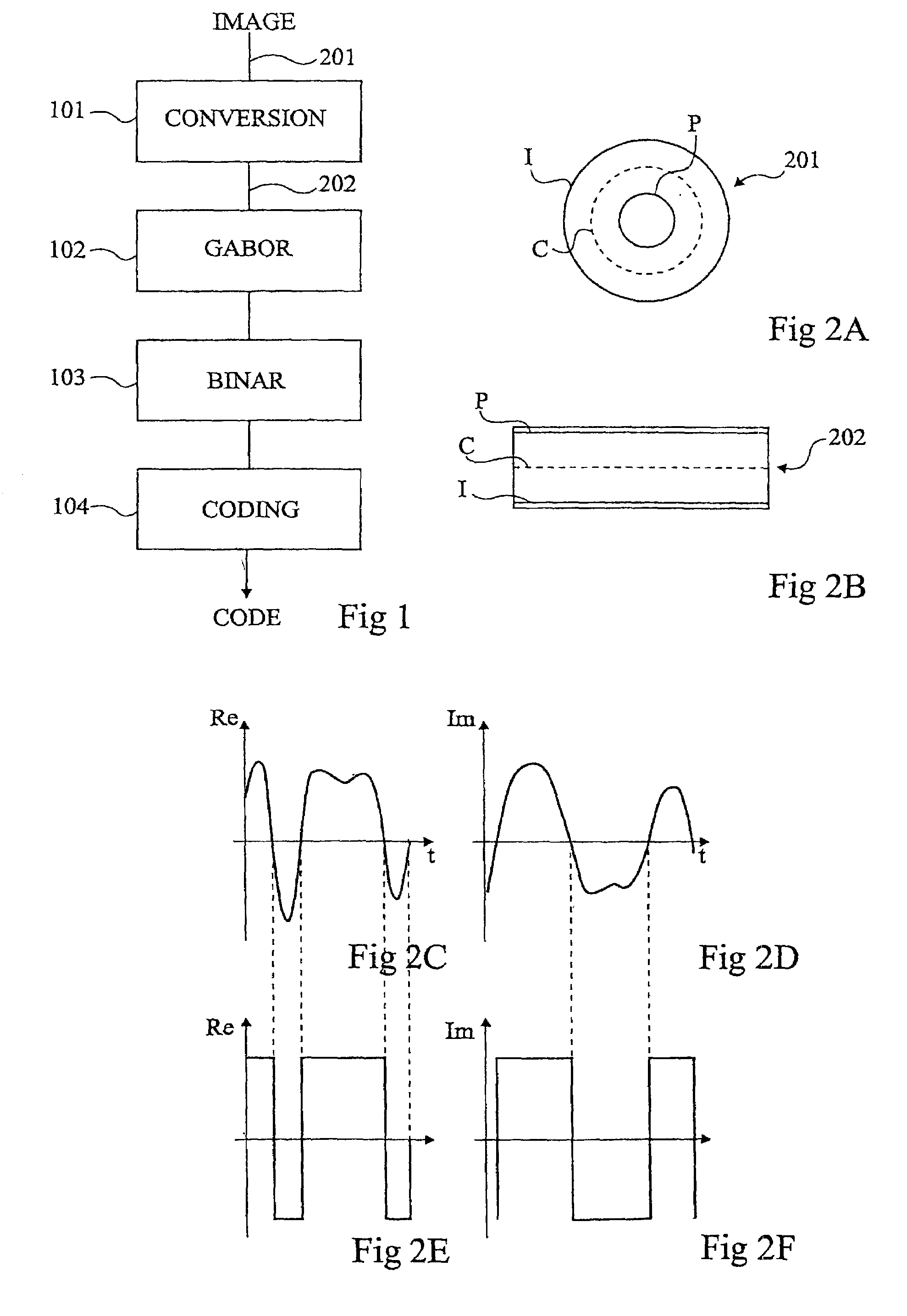
[0052]For clarity, the same elements have been designated with same references in the different drawings. Further, FIGS. 2A to 2F are not drawn to scale.

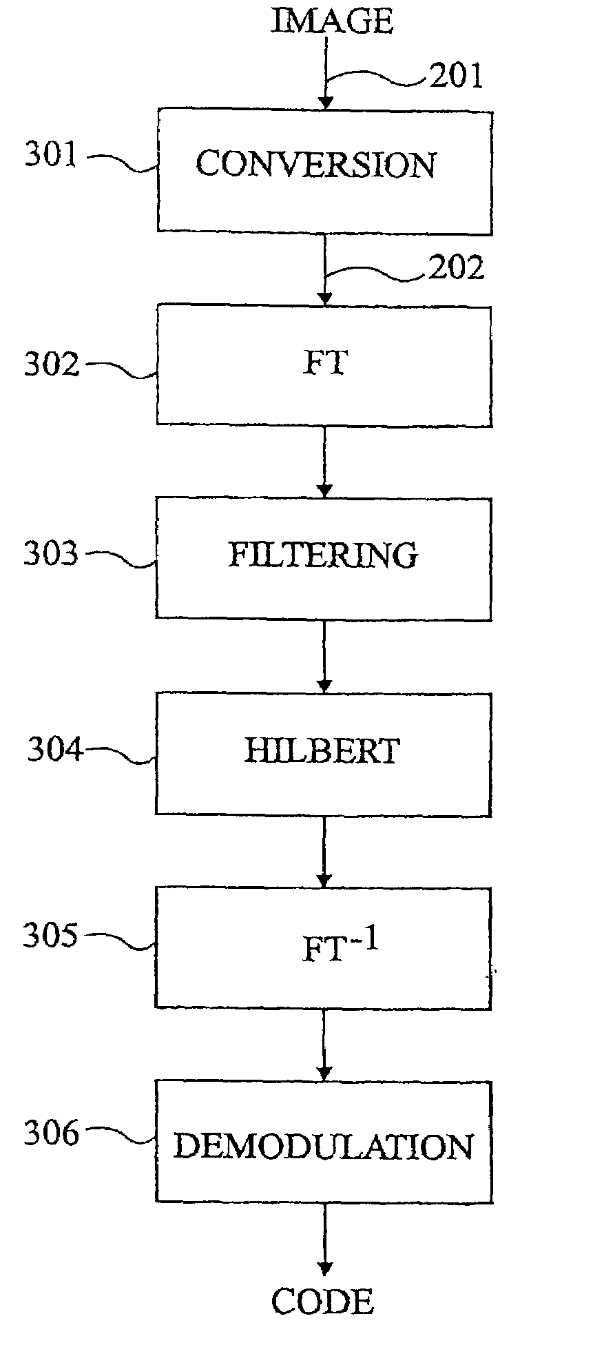
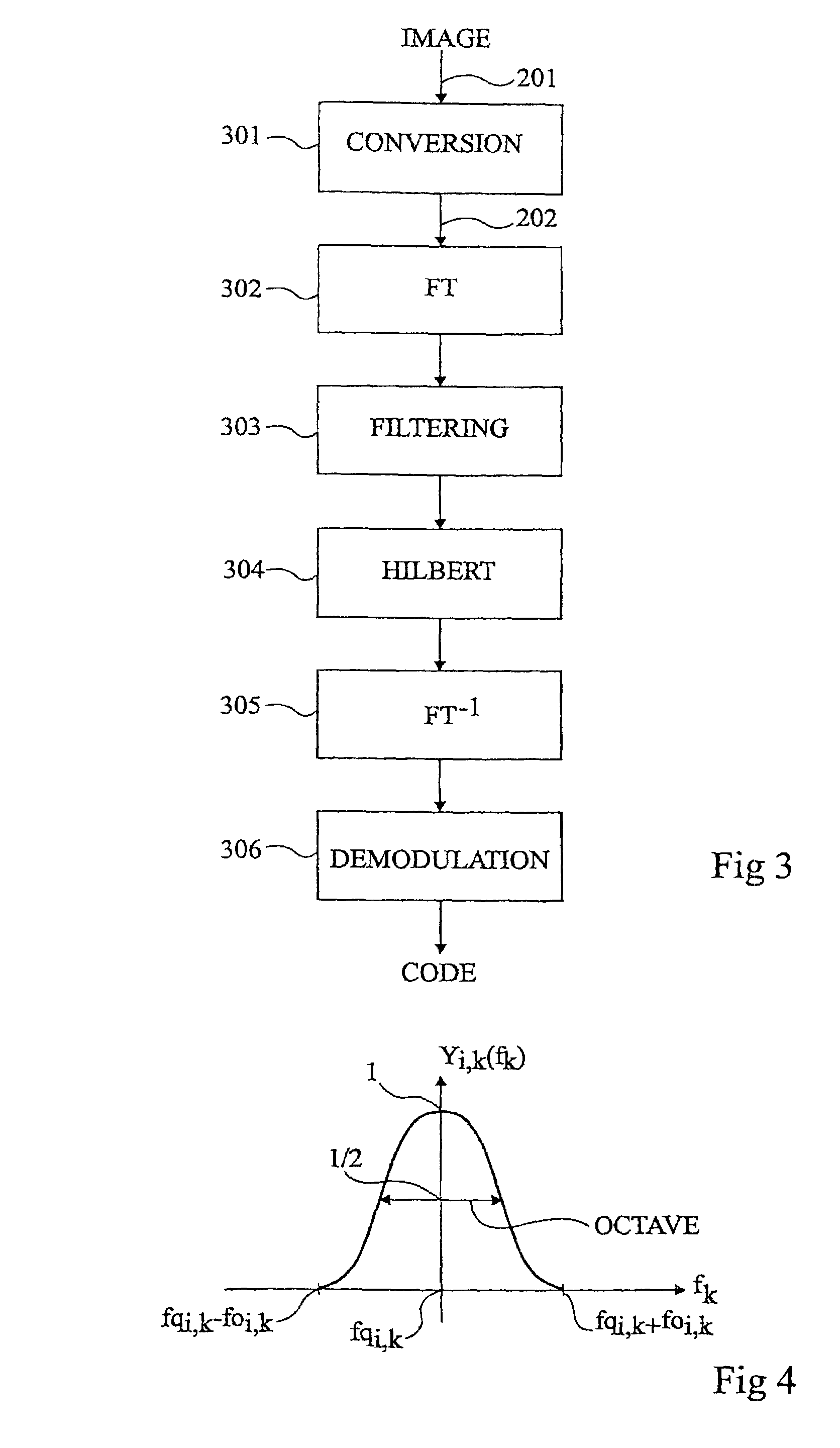
[0053]A coding mode of an iris or any other ring-shaped element including a texture, that is, characteristic information varying more significantly on concentric circles than along radial directions, is described hereafter in relation with FIGS. 3 and 4.

[0054]A digital image IMAGE to be processed includes a ring-shaped element to be coded, here, an iris, similar to that previously described in relation with FIG. 2A.

[0055]First, at block 301 (CONVERSION), the general ring shape of the iris is transformed into a rectangular shape 202 of FIG. 2B. This is done by converting the cartesian coordinates of the iris into polar coordinates, by means of a polar conversion at constant angle.

[0056]At the next step, at block 302 (FT), converted image 202 of FIG. 2B is transferred from the space field to the frequency field by a Fourier transform....


PUM


Abstract

A method for coding in frequency, module and phase a digital representation, in the space field, of a ring-shaped element, including the steps of: applying to any point of the element a polar conversion at constant angle, whereby the element is unfolded in rectangular form; transferring, to the frequency field, any point of the converted rectangular shape by means of a Fourier transform; filtering the discrete data resulting from the transfer by means of at least one real, bidimensional, band-pass filter, oriented along the phase axis; applying a Hilbert transform to the filtering results; applying an inverse Fourier transform to the results of the Hilbert transform; and extracting phase and module information in the space field.

Description

BACKGROUND OF THE INVENTION[0001]1. Field of the Invention[0002]The present invention relates to a method for coding a ring-shaped element of a digital image. More specifically, the present invention relates to a method for coding such an element in which the “useful” information is ring-shaped or circular, that is, where the information to be coded varies according to the angular position in concentric circles.[0003]2. Discussion of the Related Art[0004]An example of application of the present invention is the coding of the iris of an eye in a digital image in a recognition process. On the one hand, the iris of an eye is a ring-shaped element delimited by the cornea and by the pupil. On the other hand, an iris is characterized by its texture, which is a set of three-dimensional patterns of bumps and holes, each pattern having in the iris a radial direction. Such a texture translates, upon digital two-dimensional acquisition, as the alternation of light and dark areas. The texture v...

Claims


Application Information

Patent Timeline
IPC IPC(8): G06K9/36G06T7/00G06K9/00G06K9/48G06K9/52H04N1/41H04N7/30
CPCG06K9/0061G06K9/522G06K9/482G06V40/193G06V10/478G06V10/431
Inventor TISSE, CHRISTEL-LOICBARBEYRAC, DAMIEN
Owner STMICROELECTRONICS SRL
Why Eureka
Try Eureka