Transfer fixing apparatus

a technology of fixing apparatus and transfer, which is applied in the direction of electrographic process apparatus, ohmic resistance heating, instruments, etc., can solve the problems of 63121 not solving problems and the structure does not show effective application in such a case, and achieve the effect of reducing adverse heating influences

Inactive Publication Date: 2006-04-18
RICOH KK
View PDF7 Cites 61 Cited by
  • Summary
  • Abstract
  • Description
  • Claims
  • Application Information

AI Technical Summary

Benefits of technology

[0010]It is an object of the present invention to provide a novel fixing apparatus reducing adverse heating influences to an intermediate transfer member during an image transfer ope

Problems solved by technology

However the structure published in JP 10-63121 does not solve problems associated with transferring and fixing the toner image

Method used


Image

  • Transfer fixing apparatus
  • Transfer fixing apparatus
  • Transfer fixing apparatus

Examples


first embodiment

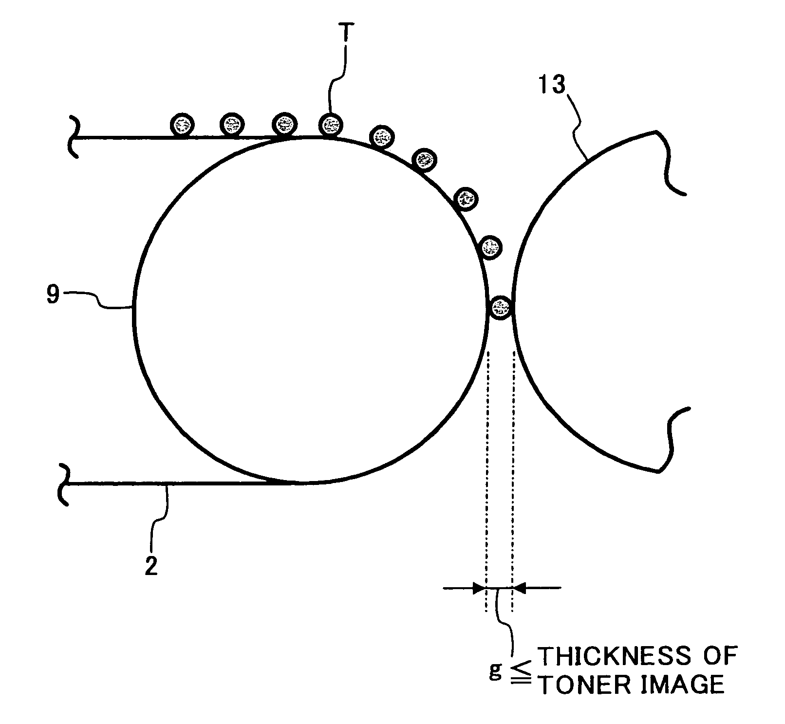
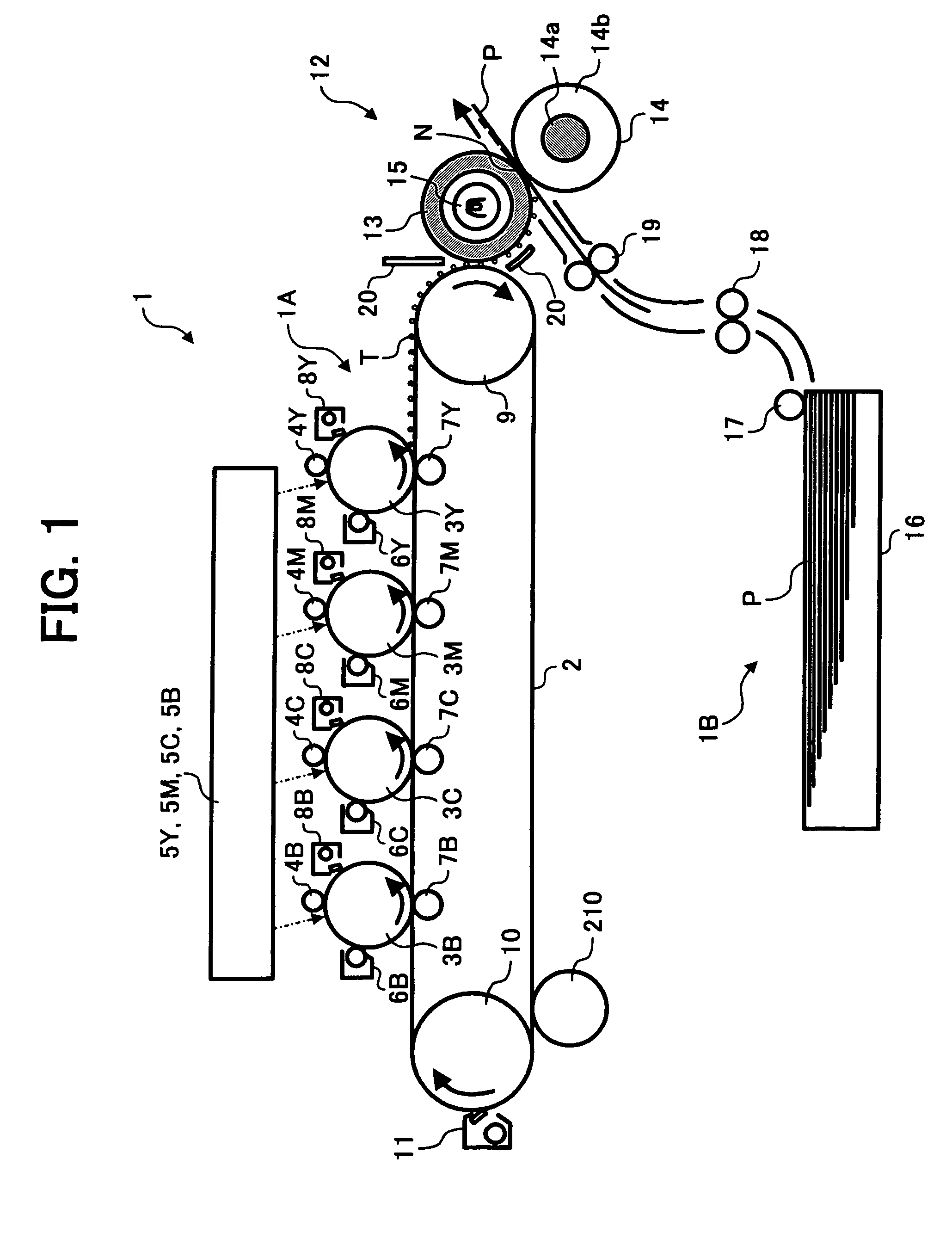
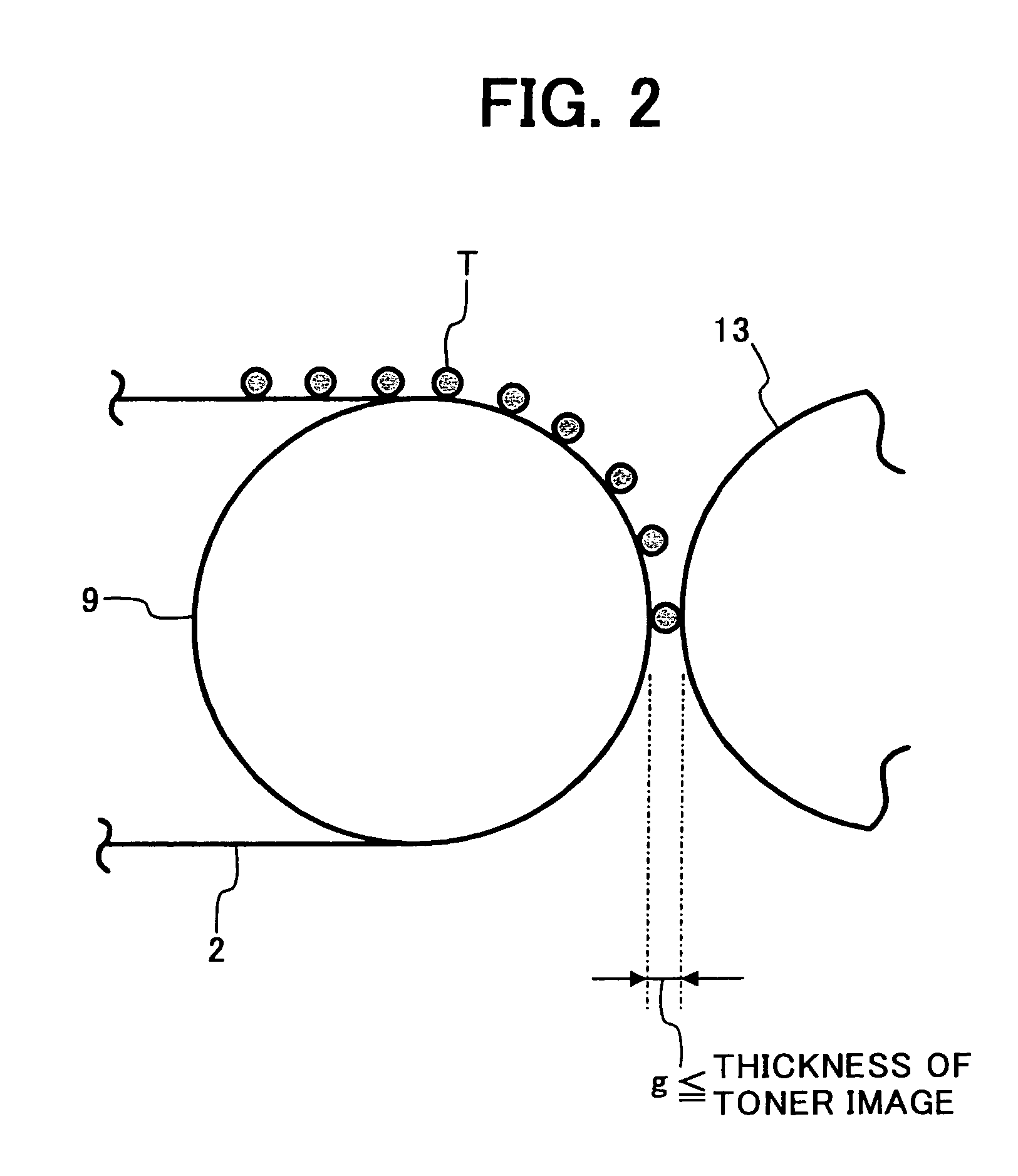
[0073]FIG. 1 is a schematic front view showing a color copier 1, of a tandem type, as an example of an image forming apparatus according to the present invention. The present invention is directed to other types of image forming apparatuses, as would be clearly understood by those of ordinary skill in the art. The color copier 1 includes an image forming unit 1A located in the middle of the apparatus, a sheet feeder unit 1B located under the image forming unit 1B, and an image scanning unit (not illustrated) located above the image forming unit 1A.

[0074]The image forming unit 1A includes an intermediate transfer belt 2 with a transfer surface extending horizontally as an intermediate transfer member, and image forming members 3Y, 3M, 3C, 3B along and above the transfer surface of the intermediate transfer belt 2 as toner image forming devices. The image forming members 3Y, 3M, 3C, 3B hold respective color toners of yellow, magenta, cyanogen, black, which we relate as complementary c...

second embodiment

[0090]FIG. 4 is a schematic front view showing a In this embodiment, at a portion inside the intermediate transfer belt 2 facing the transfer fixing roller 13 are arranged a pair of bias rollers 22, 23 as a bias supplying member. The pair of bias rollers 22, 23 support the intermediate transfer belt 2 and supply bias onto the intermediate transfer belt 2. The pair of the bias rollers 22, 23 are formed by an elastic conductor material. Between the pair of resist rollers 19 and the nip N in the direction of the conveying record medium, a heater 25 is provided as a record medium heating member. The heater 25 heats the record medium P before it reaches the nip N. The transfer fixing roller 13, the halogen heater 15, and the heater 25 are individually exchangeable.

[0091]In this embodiment, it is possible to better control the interaction between the toner image and the record medium P, because the record medium P is independently heated by the heater 25, and thereby heating of the toner...

third embodiment

[0101]FIG. 9 is a schematic front view showing a In this embodiment a transfer fixing member 27, which is formed as a belt or a sheet, is flexible. The transfer fixing member 27 is supported by a supporting member 29, a supporting roller 31, and a heating roller 33. The supporting member 29 includes a metallic base 29a and an elastic layer 29b. The supporting roller 31 includes a halogen heater 32 as a heating member. The transfer fixing member 27 rotates by the pressing roller 14 rotating. In this embodiment, it is possible to heat the toner image longer because the toner image is heated on the fixing member 27.

[0102]FIG. 10 is a control block view showing this third embodiment. The intermediate transfer belt 2 includes a controller 52, an operating panel 53 including a switch 54, and a transfer fixing member driving motor 55 as a distance changing member. The operating panel 53 outputs a signal according to operating the switch 54 to the controller 52, and inputs a signal from th...


PUM


Abstract

A transfer fixing apparatus including an intermediate transfer member having an outer surface onto which a toner image is transferred, a transfer fixing member having an outer surface onto which the toner image is transferred by the intermediate transfer member, a heating member configured to heat the toner image on the outer surface of the transfer fixing member, and an opposite member formed opposite the transfer fixing member. A nip is formed between the transfer fixing member and the opposite member, the toner image being fixed onto the recording medium while passing through the nip. The transfer member is separated by a space from the intermediate transfer member by a thickness of the toner image.

Description

CROSS-REFERENCE TO PRIORITY DOCUMENTS[0001]The present document is based on and claims priority of JPAP 2002-196,040 filed Jul. 4, 2002, JPAP 2002-249,282, filed Aug. 28, 2002, and JPAP 2003-154,828 filed May 30, 2003, the entire contents of each of which are hereby incorporated herein by reference.BACKGROUND OF THE INVENTION[0002]1. Field of the Invention[0003]The present invention relates to a fixing apparatus and a fixing method both of which fix a toner image onto a record medium. The present invention also relates to an image forming apparatus such as a copier, printer, facsimile, or other fixing apparatus, and an image forming method and a record medium recycling method.[0004]2. Discussion of the Background[0005]A background image forming apparatus such as a copier, a facsimile, or a printer fixes a toner image onto a record medium with heat, to make a copied or a recorded medium. The toner image is fixed onto the record medium, because the toner melts and softens and permeate...

Claims


Application Information

Patent Timeline
IPC IPC(8): G03G15/16G03G15/20G03G15/00G03G9/08G03G15/24G03G21/00H05B3/00
CPCG03G15/167G03G15/24G03G2215/0119G03G2215/2074G03G2215/1695
Inventor TAKASHI, FUJITAHISASHI, KIKUCHISHIGEO, KUROTAKATOSHIHIKO, BABAKATSUHIRO, ECHIGOATSUSHI, NAKAFUJIHIROKAZU, IKENOUEYUKIMICHI, SOMEYAHIROYUKI, KUNII
Owner RICOH KK
Why Eureka
Try Eureka