Method of calculating exciting coefficients for circular array antenna and radio unit utilizing the same

a circular array antenna and radio unit technology, applied in the direction of individually energised antenna arrays, wireless communication, polarisation/directional diversity, etc., can solve the problems of limited method, inability to obtain desired antenna pattern, and limited method disclosed

Inactive Publication Date: 2006-04-18
PANASONIC CORP
View PDF8 Cites 12 Cited by
  • Summary
  • Abstract
  • Description
  • Claims
  • Application Information

AI Technical Summary

Problems solved by technology

In recent years, the number of users of mobile communications including portable telephones has grown remarkably, presenting a problem of how to effectively use frequencies of radio waves used for transmission and reception.
The method disclosed in this paper, however, is limited to cases where an ar

Method used


Image

  • Method of calculating exciting coefficients for circular array antenna and radio unit utilizing the same
  • Method of calculating exciting coefficients for circular array antenna and radio unit utilizing the same
  • Method of calculating exciting coefficients for circular array antenna and radio unit utilizing the same

Examples


first exemplary embodiment

[0022

[0023]The first exemplary embodiment details a calculating method applied to cases where the number of antenna elements is even (2M).

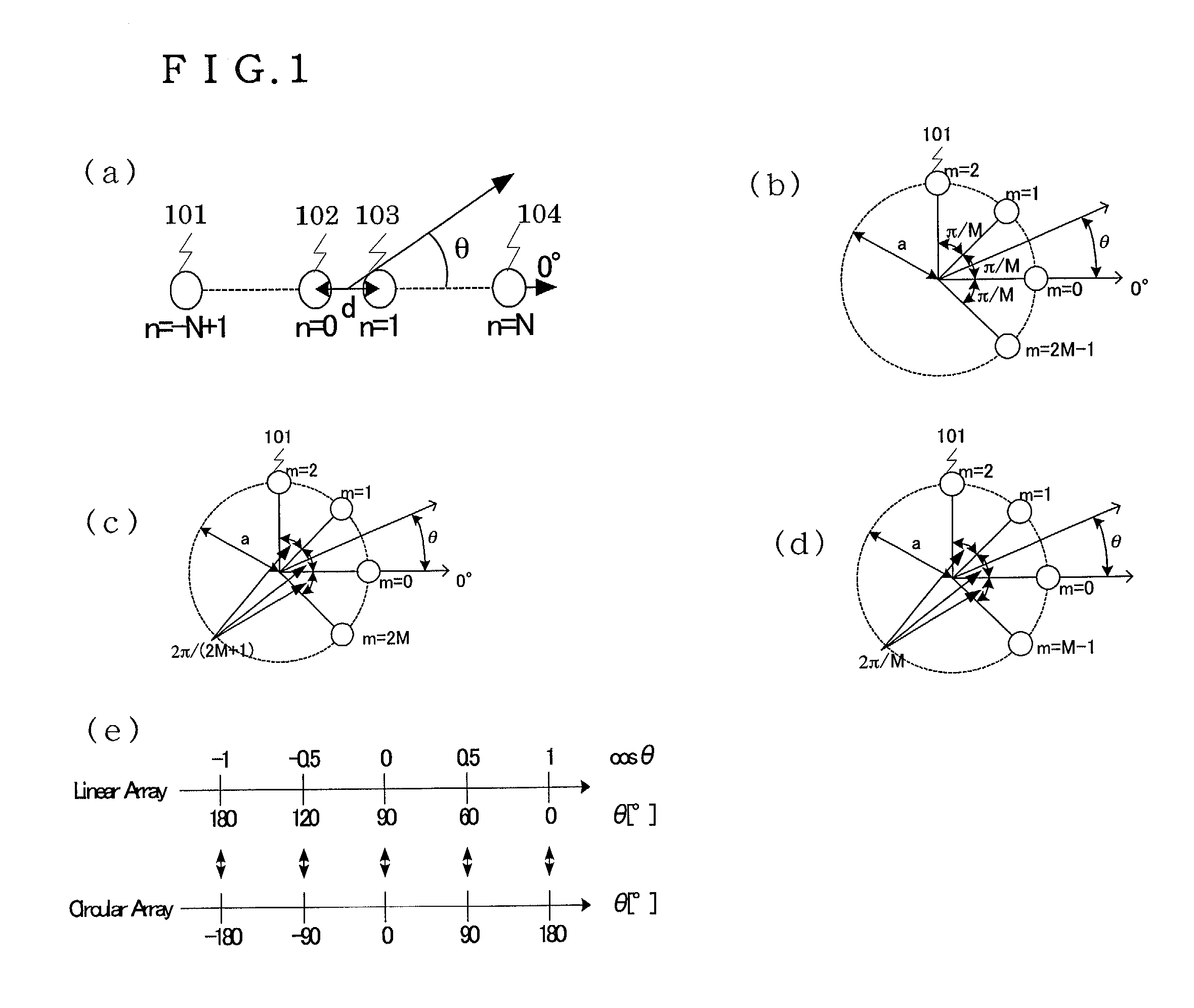
[0024]FIG. 1(a) shows an arrangement of antenna elements, the number of which is even (2N), of a linear array antenna. In FIG. 1(a), 2N antenna elements 101, 102, 103, 104 are disposed on a straight line at intervals of distance d with antenna element 101 disposed at n=−N+1. Array factor E0(θ) representing an antenna pattern of this linear array antenna, generally, can be expressed as:

[0025]E0⁡(θ)=∑n=-N+1N⁢Bn⁢ⅇj⁢2⁢π⁢⁢dλ⁢⁢2⁢(2⁢n-1)⁢cos⁢⁢θ⁢⁢or(1)E0⁡(θ)=∑n=-NN-1⁢Bn⁢ⅇj⁢2⁢π⁢⁢dλ⁢⁢2⁢(2⁢n-1)⁢cos⁢⁢θ(2)

where Bn designates an amplitude and a phase of antenna element n, d is a spacing between the antenna elements, θ is an angle between a beam direction of the antenna pattern and a direction of the linear array (the direction of 0°), and λ is a wavelength of an using radio wave.

[0026]Equation (1) applies to the case of FIG. 1(a) where first antenna element 101...

second exemplary embodiment

[0058

[0059]The second exemplary embodiment details a calculating method applied to cases where the number of antenna elements is odd (2M+1).

[0060]FIG. 1(c) shows an arrangement of antenna elements, the number of which is odd, of a circular array antenna. Antenna elements 101 are disposed counterclockwise at uniform angular intervals of 2π / (2M+1) along a circle with radius a. Specifically, first antenna element 101 is disposed at m=0 (an origin point in the direction of 0° ), and subsequent antenna elements 101 are disposed at m=1, m=2, . . . , m=2M, respectively. The present embodiment differs from the first exemplary embodiment in that a different equation is used for finding an array factor.

[0061]When the number of antenna elements of a linear array antenna is 2N+1, array factor E0(θ) can be expressed as:

[0062]E0⁡(θ)=∑n=-NN⁢Bn⁢ⅇj⁢⁢2⁢πλ⁢nd⁢⁢cos⁢⁢θ(15)

where Bn designates an amplitude and a phase of antenna element n, d is a spacing between the antenna elements, θ is an angle between...

third exemplary embodiment

[0066

[0067]The third exemplary embodiment details a method of calculating excitation coefficients for a circular array antenna having an arbitrary number of antenna elements. FIG. 1(d) shows an arrangement of antenna elements, the number of which is arbitrary (M), of a circular array antenna. Antenna elements 101 are disposed counterclockwise at uniform angular intervals of 2πfM along a circle having radius a with first antenna element disposed at an origin point (in the direction of 0°).

[0068]The present embodiment differes from the first exemplary embodiment in that a different equation is used for finding an array factor. When the number of antenna elements of a linear array is N, array factor E0(θ) can be expressed as:

[0069]E0⁡(θ)=∑n=0N-1⁢Bn⁢ⅇj⁢⁢2⁢πλ⁢nd⁢⁢cos⁢⁢θ(17)

[0070]When N is an even number, that is, N=2L, array factor E0(θ) can be expressed as:

[0071]E0⁡(θ)=∑n=-L+1L⁢Bn⁢ⅇj⁢2⁢πλ⁢nd⁢⁢cos⁢⁢θ⁢⁢or⁢⁢∑n=-LL-1⁢Bn⁢ⅇj⁢2⁢πλ⁢nd⁢⁢cos⁢⁢θ(18)

[0072]When N is an odd number, that is, N=2L+1, a...


PUM


Abstract

A method of calculating coefficients determining excitation amplitudes and phases for obtaining a desired antenna pattern of a circular array antenna comprising a plurality of antenna elements disposed circularly. Coefficients for a linear array antenna having the same number of antenna elements as the circular array antenna are determined by a Fourier series expansion in integral limits calculated from a beam direction and a beam width that are estimated from incoming radio waves and then are transformed into the coefficients for the circular array antenna. With this method, the beam direction and the beam width of the antenna pattern of the circular array antenna can be set at will. Consequently, this method enables adaptive control of sectored beams of sectored antennas at a base station or the like used for a mobile communication system, thus enhancing efficiency of the use of the antennas.

Description

FILED OF THE INVENTION[0001]The present invention relates to a method of calculating excitation coefficients for a base station antenna used for mobile communications or the like. The present invention also relates to a radio unit utilizing the calculating method.BACKGROUND OF THE INVENTION[0002]In recent years, the number of users of mobile communications including portable telephones has grown remarkably, presenting a problem of how to effectively use frequencies of radio waves used for transmission and reception. Techniques for the effective use of the frequencies include reduction of the radius of each cell having a base station at its center, antenna sectorization and the like. At present, sectored antennas currently used at the base station each has a fixed antenna pattern. If the antenna pattern of each of the sectored antennas can be adaptively varied, an optimum beam can be formed in accordance with traffic which varies momentarily, so that the effective use of the frequenc...

Claims


Application Information

Patent Timeline
IPC IPC(8): H04Q7/20H01Q1/24H01Q3/26H01Q21/20H04B7/10
CPCH01Q1/246H01Q21/20H01Q3/26
Inventor MIYANO, KENTAROFUKAGAWA, TAKASHIKISHIGAMI, TAKAAKIHASEGAWA, MAKOTO
Owner PANASONIC CORP
Why Eureka
Try Eureka