
System for deriving desired output frequency by successively dividing clock signal frequency by ratios obtained by dividing clock signal frequency by common divisor and specific integer

a clock signal frequency and ratio technology, applied in the field of signal generation, can solve the problems of complex logic, large number of oscillators, and low output frequency of clock signal frequency, and achieve the effect of reducing jitter

Active Publication Date: 2006-04-18
SILICON VALLEY BANK +1
View PDF4 Cites 2 Cited by
  • Summary
  • Abstract
  • Description
  • Claims
  • Application Information

AI Technical Summary

Benefits of technology

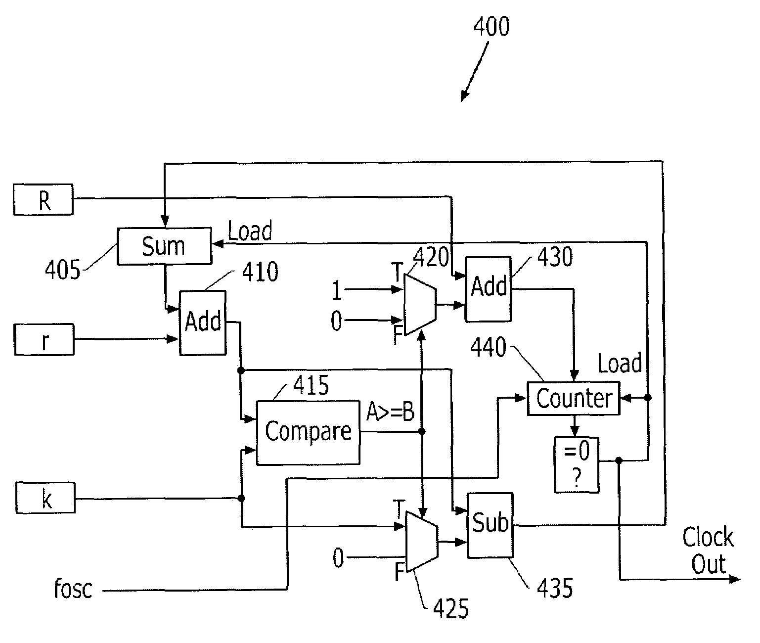
[0007]In further embodiments of the present invention, driving the counter comprises initializing a sum to a value less than y and then repetitively performing the following operations at the clock signal frequency: The sum is incremented by x. If the sum is less than y, then the count value of the counter is set to R. If the sum is not less than y, then the count value of the counter is set to R+1 and the sum is decremented by y. Jitter represents deviation of the clock edges from their ideal locations and may amount to one period of the clock signal. Advantageously, the present invention may reduce jitter by allowing computations to be performed at the lower generated signal frequency so that the clock signal frequency may be increased.

Problems solved by technology

Unfortunately, this may result in a relatively large number of oscillators; therefore, in practice, only a subset of the harmonic frequencies is typically provided.
Such signal generators, however, may be less desirable for use in generating a large number of different frequencies as a set of counter ratios and a pattern would typically have to be stored for each frequency to be generated.
This complex logic, however, operates at the high clock signal frequency.

Method used


Image

  • System for deriving desired output frequency by successively dividing clock signal frequency by ratios obtained by dividing clock signal frequency by common divisor and specific integer
  • System for deriving desired output frequency by successively dividing clock signal frequency by ratios obtained by dividing clock signal frequency by common divisor and specific integer
  • System for deriving desired output frequency by successively dividing clock signal frequency by ratios obtained by dividing clock signal frequency by common divisor and specific integer

Examples


Embodiment Construction

[0014]While the invention is susceptible to various modifications and alternative forms, specific embodiments thereof are shown by way of example in the drawings and will herein be described in detail. It should be understood, however, that there is no intent to limit the invention to the particular forms disclosed, but on the contrary, the invention is to cover all modifications, equivalents, and alternatives falling within the spirit and scope of the invention as defined by the claims. Like reference numbers signify like elements throughout the description of the figures. It will also be understood that when an element is referred to as being “connected” or “coupled” to another element, it can be directly connected or coupled to the other element or intervening elements may also be present. In contrast, when an element is referred to as being “directly connected” or “directly coupled” to another element, there are no intervening elements present.

[0015]The present invention may be ...


PUM


Abstract

A signal is generated by providing a clock signal having a frequency (fosc). The clock frequency fosc is arithmetically divided by an output frequency (fo) associated with the signal to obtain a ratio R and a remainder given by x / y. The signal is derived from the clock signal by successively dividing the frequency (fosc) of the clock signal by one of R and R+1, such that a fraction of times that the frequency (fosc) of the clock signal is divided by R is given by 1-x / y and a fraction of times that the frequency (fosc) of the clock signal is divided by R+1 is given by x / y. In particular, the signal is derived by driving a counter using the clock signal to a count value of one of R and R+1, such that a fraction of times that the counter is driven to a count value of R is given by 1-x / y and a fraction of times that the counter is driven to a count value of R+1 is given by x / y.

Description

RELATED APPLICATIONS[0001]This application claims the benefit of Provisional Application No. 60 / 347,606, filed Jan. 10, 2002, the disclosure of which is hereby incorporated herein by reference.BACKGROUND OF THE INVENTION[0002]The present invention relates to signal generation, and, more particularly, to deriving one or more lower frequency signals from a higher frequency clock signal.[0003]Conventional signal generators may use multiple oscillators to derive harmonic frequency signals from a clock signal. Unfortunately, this may result in a relatively large number of oscillators; therefore, in practice, only a subset of the harmonic frequencies is typically provided.[0004]Other conventional signal generators may generate signals having frequencies that are not sub-harmonics of a clock signal through the use of alternate ratio counters. These signal generators may use the clock signal to drive two counters whose count differs by one. By alternately combining the outputs of these two ...

Claims


Application Information

Patent Timeline
Patent Type & Authority Patents(United States)
IPC IPC(8): G06F1/00G06G7/60G06F7/68
CPCG06F7/68
Inventor RADCLIFFE, JERRY KYLE
Owner SILICON VALLEY BANK
Learn More