Heart cam and damper unit and opening/closing controlling device using the same

Inactive Publication Date: 2006-04-25
PIOLAX CO LTD
View PDF22 Cites 37 Cited by
  • Summary
  • Abstract
  • Description
  • Claims
  • Application Information

AI Technical Summary

Benefits of technology

[0025]In accordance with a ninth aspect of the invention, there is provided the opening/closing controlling device in which said base member has a fixing portion for fixing said opening/closing controlling device to a member to be fixed

Problems solved by technology

In addition, if the drawer portion could be pushed in speedily with a strong force, the drawer portion and an accommodating apparatus body would collide with each other strongly, and collision noise would be

Method used


Image

  • Heart cam and damper unit and opening/closing controlling device using the same
  • Heart cam and damper unit and opening/closing controlling device using the same
  • Heart cam and damper unit and opening/closing controlling device using the same

Examples


Embodiment Construction

[Detailed Description of The Invention]

[0036]Embodiments of the invention will be explained with reference to the drawings.

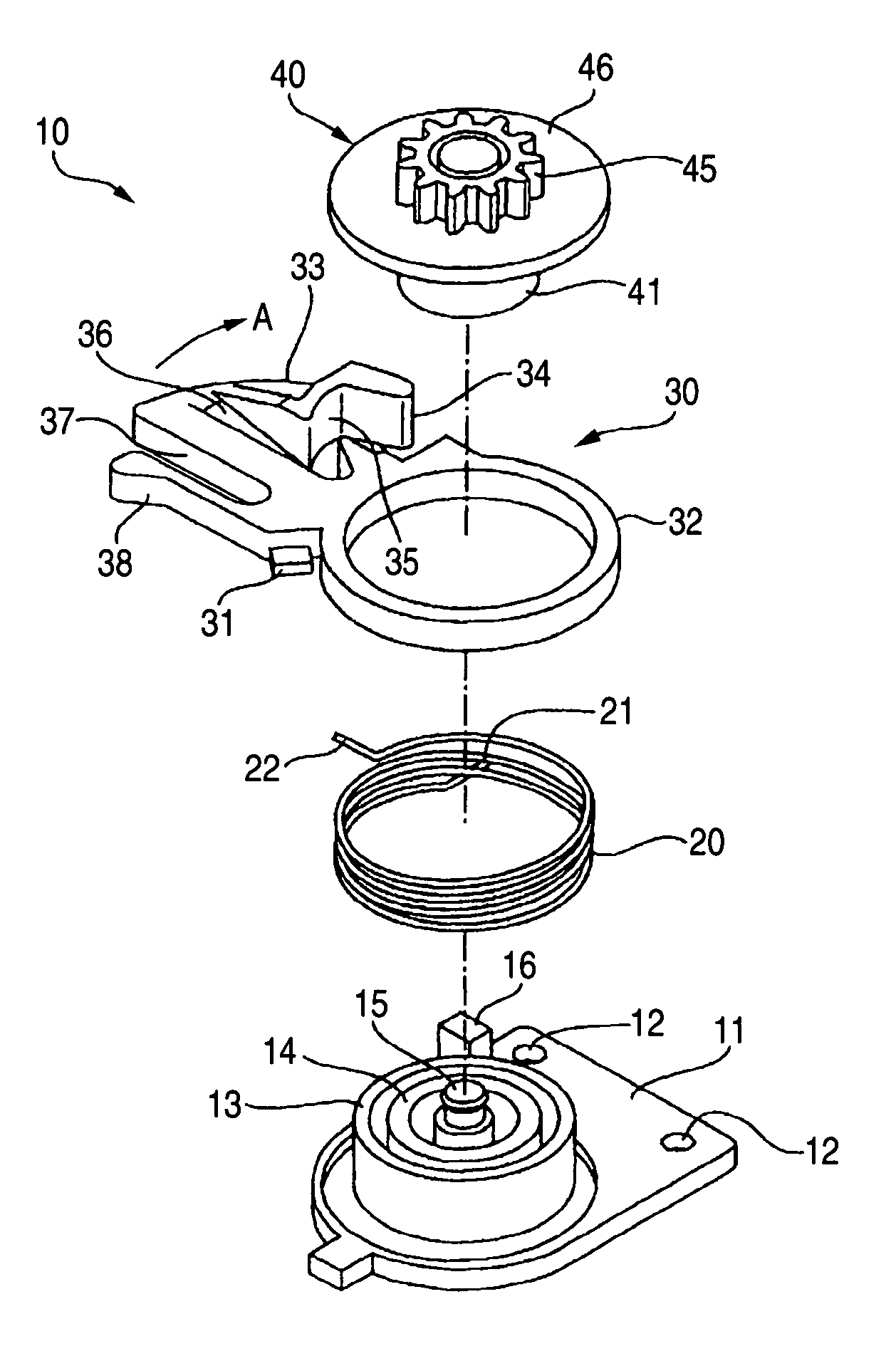
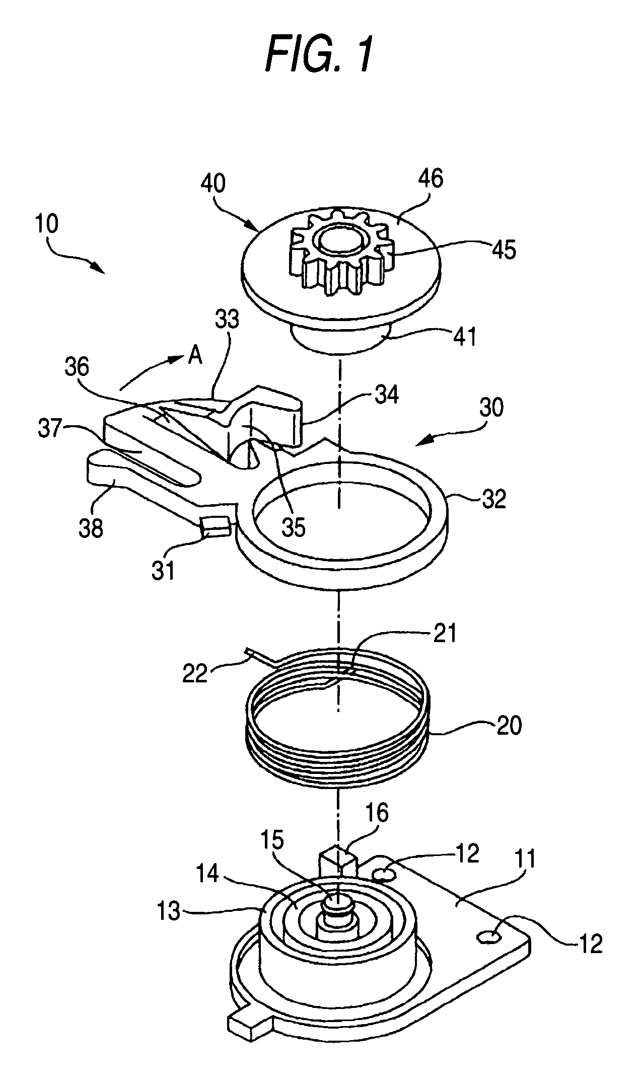
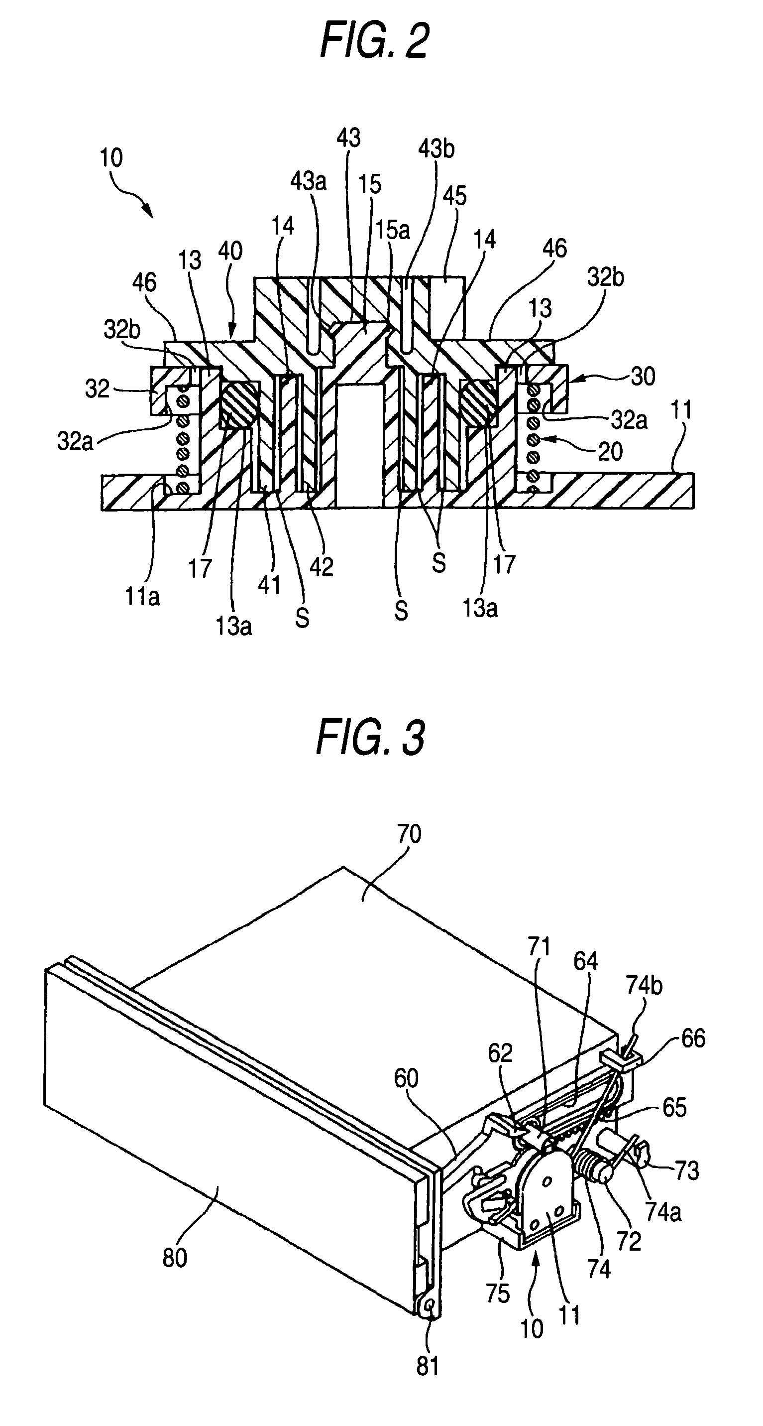
[0037]FIGS. 1 to 6B illustrate a first embodiment of an opening / closing controlling device in accordance with the invention. FIG. 1 is an exploded perspective view of a heart cam and damper unit. FIG. 2 is a cross-sectional view of the hear cam damper unit. FIG. 3 shows an embodiment of the opening / closing controlling device for a cover with respect to a housing. FIG. 4A is a side elevational view of a state that the cover of the opening / closing controlling device is closed. FIG. 4B is a side elevational view of a state that the cover is opened. FIGS. 5A, 5B, 6A, and 6B are explanatory diagrams illustrating the locking action of a heart cam.

[0038]As shown in FIGS. 1 and 2, a heart cam and damper unit 10 has a plate-like base member 11. This base member 11 has mounting holes 12 and is adapted to be screwed down to a housing 70 which will be described later. The m...


PUM


Abstract

A heart cam and damper unit includes a base member having fixed cylindrical portions and a stopper portion, a rotating member having a movable cylindrical portion which is rotatably assembled to the fixed cylindrical portion with a viscous fluid interposed between the movable cylindrical portion and the fixed cylindrical portions, and a pinion gear rotating integrally with the movable cylindrical portion, a heart cam member rotatable fitted around an outer periphery of an outwardly located one of the fixed cylindrical portion and the movable cylindrical portion, and a device interposed between the base member and the heart cam member and adapted to rotatably urge the heart cam member toward the stopper portion. The heart cam and damper unit is interposed between a main body portion and a movable portion which undergoes opening and closing action with respect to the main body portion and is constantly urged in an opening direction.

Description

BACKGROUND OF THE INVENTION[0001]1. Field of the Invention[0002]The present invention relates to a heart cam and damper unit used for the opening / closing control of a drawer-type accommodating apparatus such as an ashtray, a table or a cup holder which is mounted in a vehicle compartment, for example, as well as an opening / closing controlling device using the same.[0003]2. Description of the Related Art[0004]A drawer-type accommodating apparatus such as an ashtray, a table, a cup holder or a card holder is installed in a vehicle compartment of an automobile or the like. A push-open type lock device using a heart cam is generally adopted for such an accommodating apparatus.[0005]As such a lock device, JP-A-2002-106238 discloses a push-open type lock device for an accommodating apparatus having an opening and an opening and closing member for opening and closing this opening, which includes a hard pin member provided on one of the opening and the opening and closing member, and a cam ...

Claims


Application Information

Patent Timeline
IPC IPC(8): E05B65/44E05C19/02F16D57/02A47B88/04B60N3/08B60N3/10B60R7/06F16F9/12
CPCA47B88/047B60N3/083F16F9/125B60N3/102Y10T16/61Y10T16/276A47B88/467Y10T292/1078Y10T292/0948B60N3/08
Inventor ICHIOKA, HIROAKIMITSUEDA, TAKEOMIZUNO, TAKAKI
Owner PIOLAX CO LTD
Why Eureka
Try Eureka