Automatic tool changing device for machine tool

a technology of automatic tool changing and machine tools, which is applied in the field of automatic tool changing device for machine tools, can solve the problems of affecting the machining accuracy, the necessity of forming the air passage in the spindle, and the inability to properly fit the tool holders to the spindle, so as to achieve accurate measurement and accurate detection

Active Publication Date: 2006-04-25
FANUC LTD
View PDF26 Cites 13 Cited by
  • Summary
  • Abstract
  • Description
  • Claims
  • Application Information

AI Technical Summary

Benefits of technology

[0015]The automatic tool changing device fluid spouting means may further comprise a distance sensor for measuring distance to a periphery of the tool holder attached to the spindle, and the fluid spouting means may include means for spouting fluid toward the periphery of the tool holder to be cleaned. With this arrangement, the distance between the distance sensor and the periphery of the tool holder is accurately measured to enable accurate detection of whether or not the tool holder is properly attached to the spindle.

Problems solved by technology

Occasionally, however, the tool holder may not be fitted to the spindle properly because of foreign matter, such as swarf, adhered to contact surfaces of the spindle and the tool holder, which affects the machining accuracy.
The necessity for forming the air passage in the spindle complicates fabrication of the spindle.
This entails an additional cleaning operation for each the tool change operation, so that it accordingly takes a long time to complete the tool change, thereby lowering operation efficiency.
The cleaning method described in this document requires an air passage formed in the tool holder, which makes the tool holder costly.
Furthermore, since the existing tool holders have no air passage, the aforementioned method cannot be applied to the tool change using existing tool holders.

Method used


Image

  • Automatic tool changing device for machine tool
  • Automatic tool changing device for machine tool
  • Automatic tool changing device for machine tool

Examples


Embodiment Construction

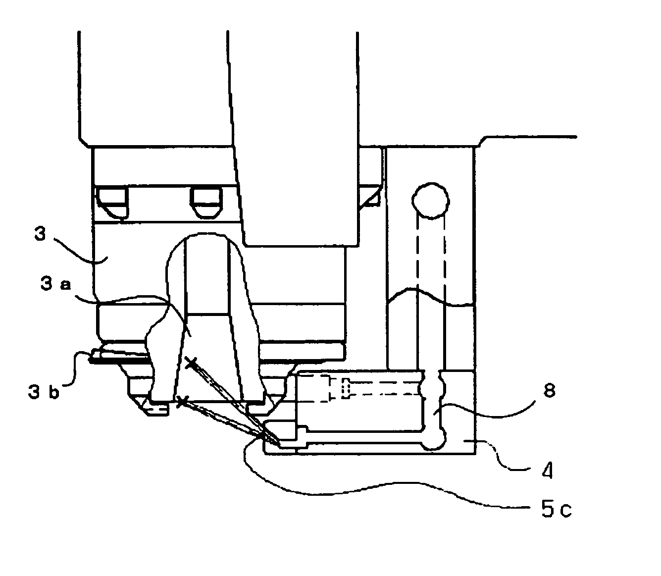
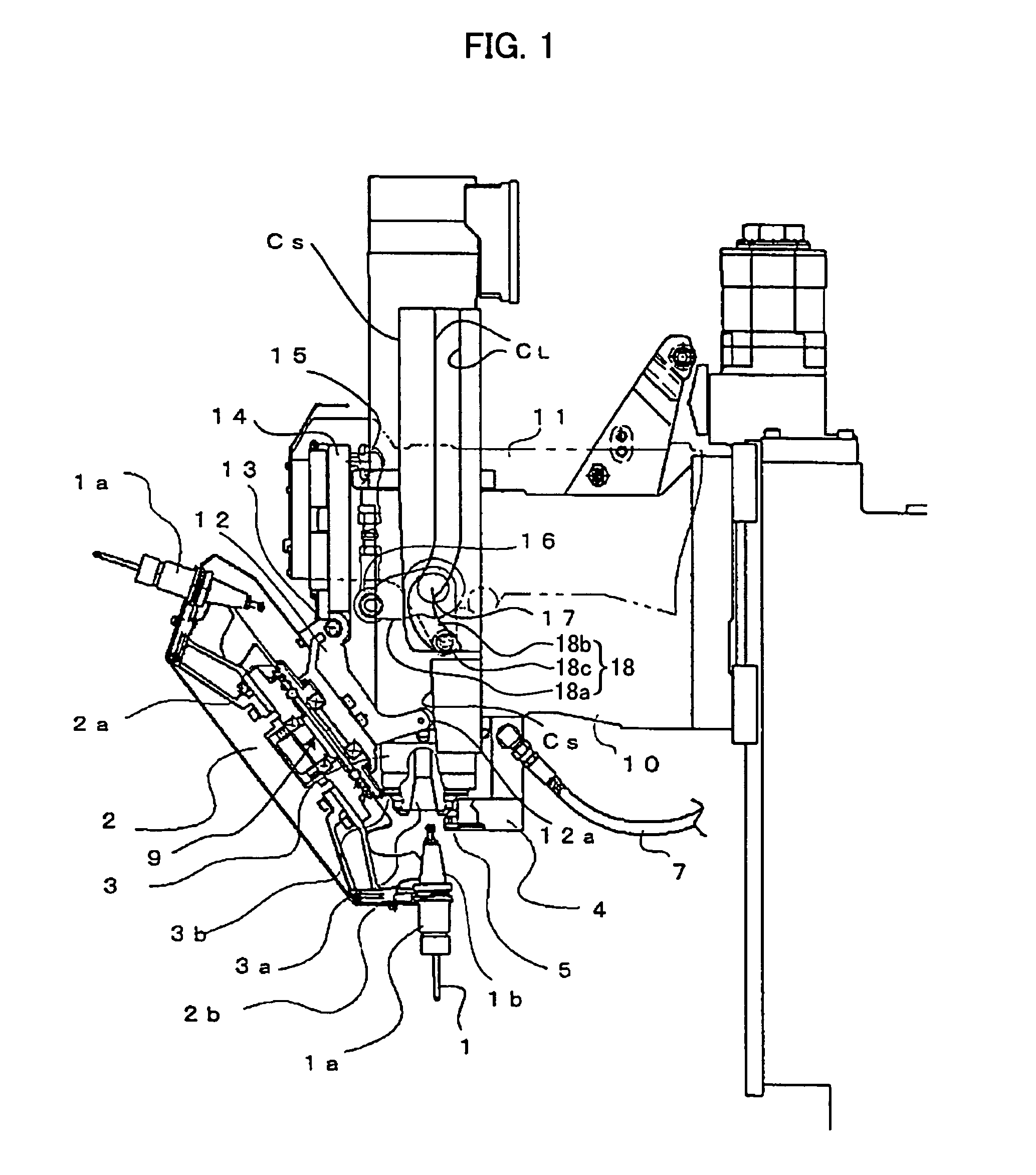
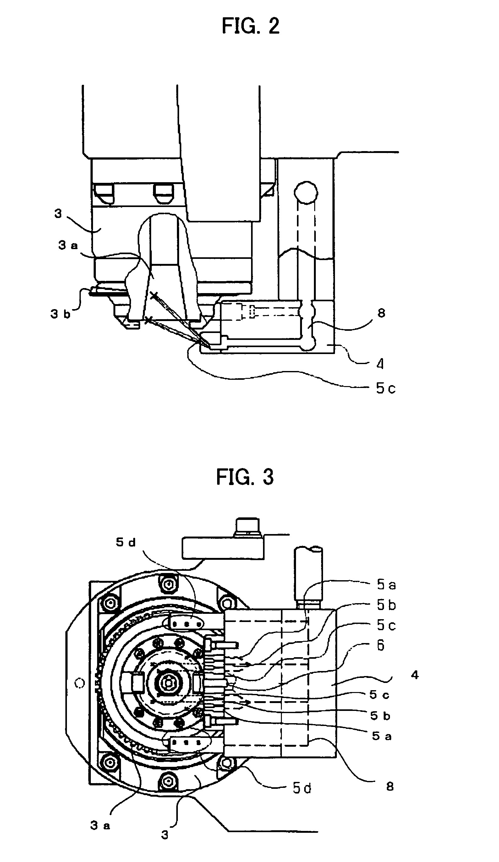
[0020]FIG. 1 is an explanatory view of a substantial part of one embodiment of an automatic tool changing device according to the present invention. The device of the embodiment is identical to one described in JP 2535479B, except that according to the embodiment, a manifold 4 and a nozzle portion 5 serving as fluid spouting means, and a pipe 7 for supplying fluid, such as a coolant, to the manifold 4 as the fluid spouting means are added to the automatic tool changing device disclosed in the above publication. First, a summary of a known part of the automatic tool changing device will be described.

[0021]The automatic tool changing device according to the embodiment comprises an arm member 11, a turret 2 having a plurality of grippers 2b on an outer circumference thereof and holding a tool holder 1a by means of the grippers 2b, a crank 12 secured onto a back face of the turret 2, first and second cams Cs, CL fastened to a spindle head, a swing roller 12a provided to the crank 12, wh...


PUM

PropertyMeasurementUnit
distanceaaaaaaaaaa
timeaaaaaaaaaa
speedaaaaaaaaaa

Abstract

An automatic tool changing device capable of cleaning a contact surface of a spindle, which is to be in contact with a tool holder, with a simple structure. The device includes a turret having a plurality of grippers on its outer circumference and holding the tool holder by means of the grippers. At the time of tool change, the grippers grip and pull out the tool holder fixed to the spindle. Rotation of the spindle causes the turret to rotate through a spindle gear, a turret gear, and a decelerating device, to thereby select a tool. At this moment, a coolant is spouted from a nozzle portion of a manifold toward a spindle taper hole in which the tool holder is interfitted and washes the taper hole. Due to the rotation of the spindle, the coolant is spouted onto the whole circumference of the taper hole, and the surface to be in contact with the tool holder is surely washed. Therefore, it is possible to perform the cleaning with a simple structure in which the nozzle portion is arranged near the spindle without machining the spindle and the tool holder.

Description

BACKGROUND OF THE INVENTION[0001]1. Field of the Invention[0002]The present invention relates to an automatic tool changing device for a machine tool.[0003]2. Description of the Related Art[0004]In case that a tool is changed, machining accuracy on a workpiece is maintained by properly fitting a tool holder onto the spindle of a machine tool. Occasionally, however, the tool holder may not be fitted to the spindle properly because of foreign matter, such as swarf, adhered to contact surfaces of the spindle and the tool holder, which affects the machining accuracy. For this reason, there has been employed a method of cleaning a surface of a taper hole of the spindle and / or a tapered portion of the tool holder as the contact surface is cleaned by removing the swarf and the like using fluid, such as air in an operation of a tool change.[0005]There is a known method in which an air nozzle is opened in the taper hole of the spindle to which the tapered portion of the tool holder is fitted...

Claims


Application Information

Patent Timeline
Patent Type & Authority Patents(United States)
IPC IPC(8): B23Q3/157B23Q11/00B23Q11/10B23Q11/12B23Q3/155
CPCB23Q3/15706B23Q11/005Y10T408/46Y10T483/1795Y10T483/15Y10T409/30392Y10T483/179Y10T483/11Y10T409/304088Y10T483/1755Y10T409/303976B23Q3/15534
Inventor FUJIMOTO, AKIHIKOSATO, NAOKIWATANABE, NORIO
Owner FANUC LTD
Why Eureka
Try Eureka