Self sealing luer receiving stopcock

a self-sealing, stopcock technology, applied in the direction of packaging foodstuffs, pharmaceutical containers, packaged goods types, etc., can solve the problems of high cost of the nascent “needle free” medical fluid access system, bacteria and fluid gaining entry into the circumferential crevice are displaced back and forth, and are not accessible to wiping, etc., to achieve precise and focused membrane stretching, thin membrane, and weaken the membrane

Inactive Publication Date: 2006-04-25
BECTON DICKINSON & CO
View PDF139 Cites 250 Cited by
  • Summary
  • Abstract
  • Description
  • Claims
  • Application Information

AI Technical Summary

Benefits of technology

[0040]The stopper preferably includes a pre-slitted portion and may be slitted from both the upper surface and the lower surface, the slits preferably do not extend completely through the stopper so that a complete seal is provided for long term storage. The upper and lower slit may be formed by slitting, and may be slitted using the “anvil and blade method”, as is known in the art, to stretch and induce a very thin membrane. Alternatively the slits may be molded, as by the providing of a projecting fine metal leaf into the stopper during molding, as is known in the art. In one preferred embodiment, the first portion of the upper slit is molded and then the lower slit is extended by inserting an anvil into the upper slit and then further slitting the lower portion using a blade to a predetermined point adjacent the upper face. In one embodiment, the lower slit is pre-molded and the anvil is sized with the approximate diameter of a luer cannula and can be inserted into the face opposite the lower slit, achieving precise and focused stretching of the membrane before the blade is advanced to extend the lower slit to further thin and weaken the membrane. Alternatively, both the upper and lower slits can be pre-molded and either the upper slit or lower slit then extended by the insertion of a luer diameter anvil into the opposing slit to stretch the membrane over the anvil and then applying a blade to further thin the membrane.
[0041]If the slits are molded, the stopper can be subsequently placed with the retainer and / or open container end in a slight state of compression so as to seal the molded slit. The upper and lower slits may be formed so that an obliquely oriented membrane separates them so that the upper slit ends adjacent an oblique membrane to facilitate more easy rupture by the advancing luer during operation. In one embodiment the membrane is positioned at a point wherein the luer tip forcefully engages only one portion of the membrane when the threads of the retainer have been well engaged with the luer lock threads so that the rupture of the membrane is facilitated by the mechanical advantage provided by the threading process against a narrow focused region of maximally stretched membrane.

Problems solved by technology

The high cost of the nascent “needle free” medical fluid access systems is well known.
Much of this cost is related to the widespread use of cannulae for penetration of septa or to the use of expensive luer activation valves and internal spike based systems.
Bacteria and fluid gaining entry into the circumferential crevice are displaced back and forth and are not accessible to wiping.
Indeed if the surface is induced into a convex configuration by transverse compression then there can be a tendency for slight gapping of the slit at the surface.
There has been a longstanding need for luer access containers which can be manufactured at a very low cost, which provide a strong bi-directional seal during and after luer penetration, which are comprised of conventional materials for which drug compatibility has been already established, and which do not require the addition of an internal spike for penetration of the stopper, which by its nature adds complexity and cost.
Also such internal spikes remain in contact with the drug once the initial activation has been performed so that issues of compatibility and the internal spike arise if the drug vial is intended for multiple access over several days as with many conventional drug vials.

Method used


Image

  • Self sealing luer receiving stopcock
  • Self sealing luer receiving stopcock
  • Self sealing luer receiving stopcock

Examples


Embodiment Construction

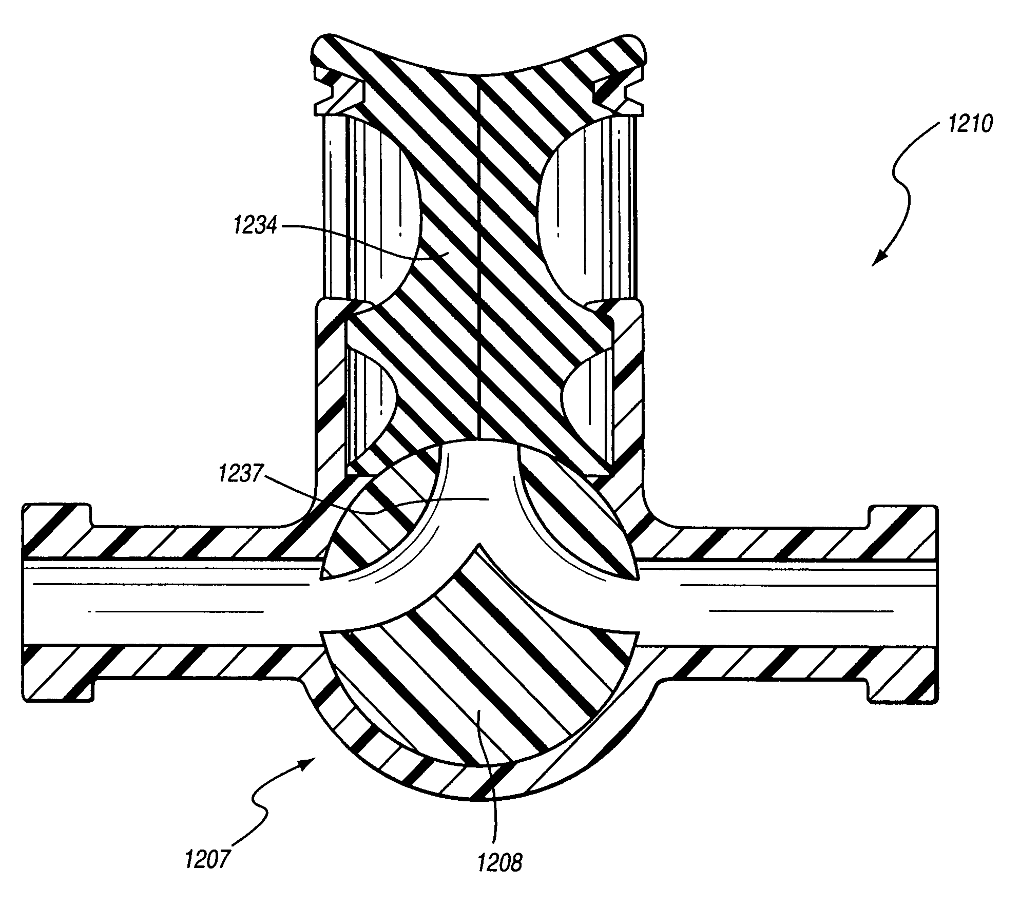
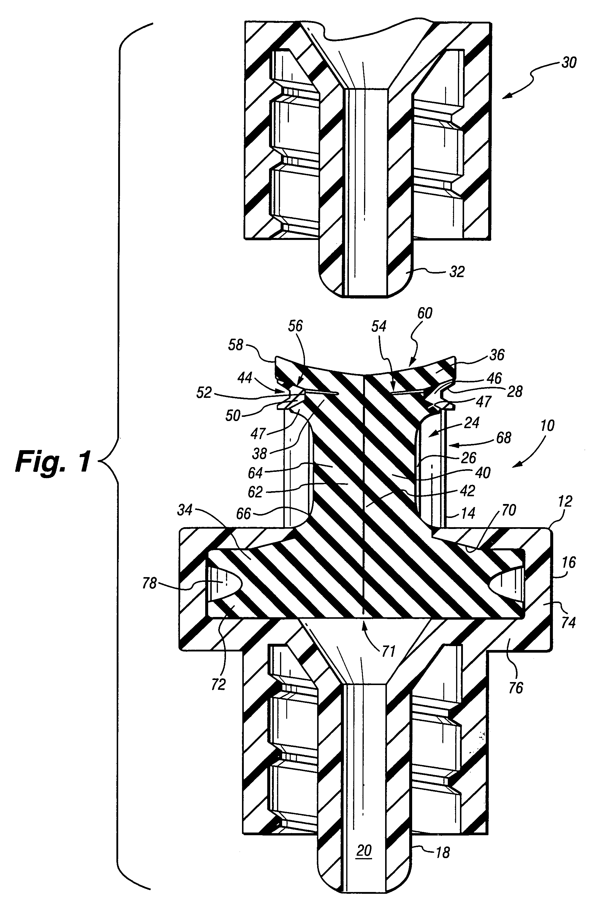
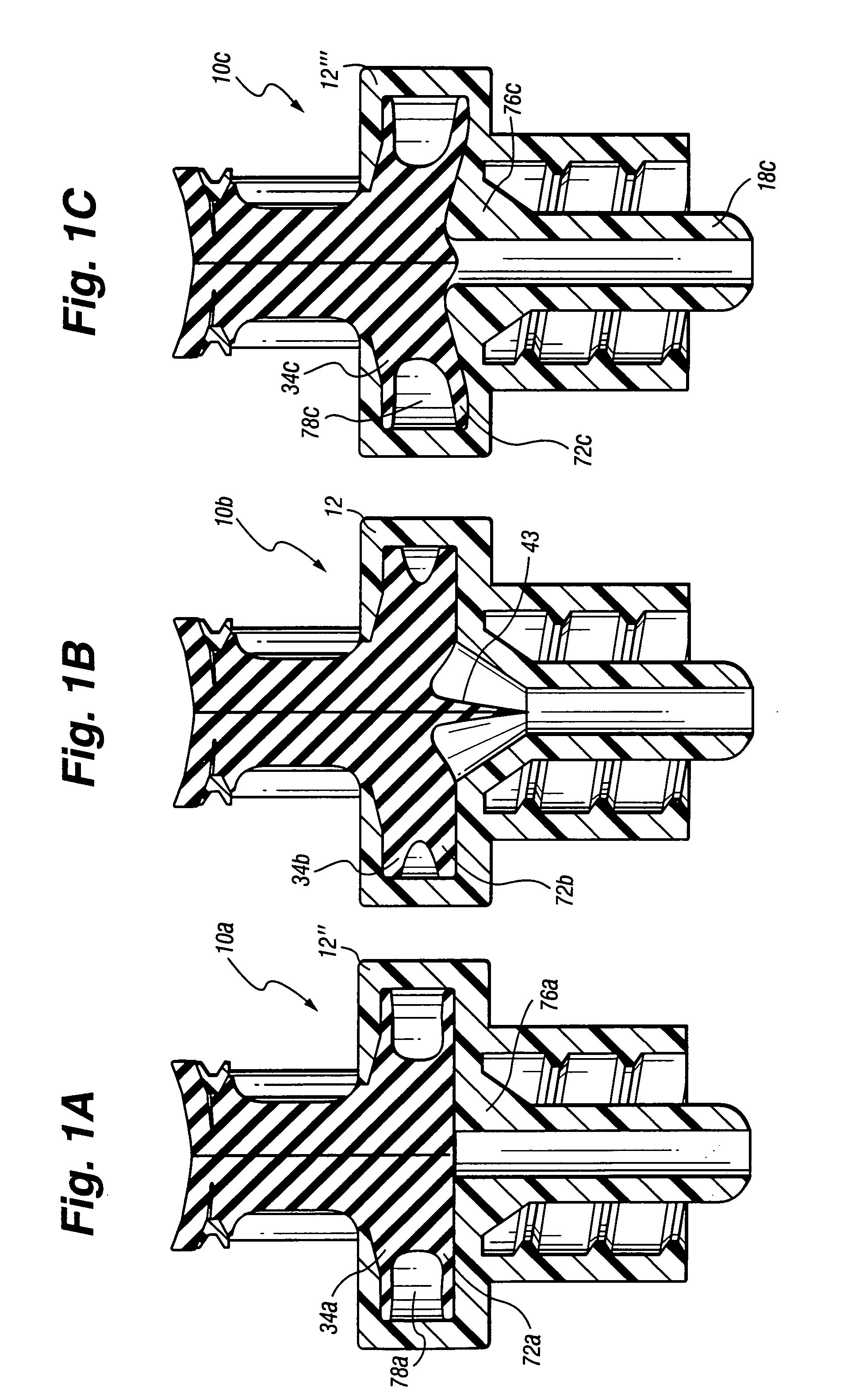
[0124]As shown in FIGS. 1, 2, and 3, the luer lock receiver 10 comprises a housing 12 including an proximal portion 14, a central portion 16, and a distal portion 18 having a distal lumen 20. The proximal portion14 has an inlet 22, and interior walls 24 defining an intermediate space or bore 26 and outer threads 28 and is sized to be threadably received into a conventional luer lock 30 with male luer tip and a surrounding female threaded end. Bore 26 is sized to receive a conventional luer cannula 32. A septum 34 has a proximal portion that, in this embodiment, includes a widened upper portion 36 and a narrower lower portion 38. The septum 34 further has an extension 40 that is received intermediate the interior walls of the housing 12. A central slit 42, sized to snugly receive the luer cannula 32, is provided to extend from adjacent the upper face of the upper portion 36, through the proximal portion of septum 34 and at least partly through the extension 40. In the embodiment of F...


PUM


Abstract

An improved luer lock receiving septum having a configuration which provides rapid and tight resealing and yet allows penetration of the septum by the luer tip with a low penetration force. The elongated septum includes an upper portion of enlarged diameter having a target surface, a central slit, and a central, lower septum extension projecting about the slit below the upper portion and into a housing so that following luer insertion there is provided sufficient room for both the laterally displaced extension of the septum, the luer taper, and the housing to be received into a conventional luer lock connector. The septum is further preferably configured to minimize or eliminate the negative pressure deflection normally associated with the withdrawal of the large diameter luer cannula from an enclosed fluid filled lumen or chamber, by substantially isolating the lumen or chamber from the septum material displacement resultant from luer insertion. In an exemplary embodiment, the luer receiving septum is provided at a port of a stop cock.

Description

[0001]This application is a continuation-in-part of U.S. patent application Ser. No. 09 / 322,037, filed May 28, 1999 now U.S. Pat. No. 6,171,287, which claims the benefit of U.S. Provisional Application Ser. No. 60 / 087,162, which was filed May 29, 1998 now abandoned, and U.S. Provisional Application Ser. No. 60 / 101,998, which was filed Sep. 28, 1998 now abandoned, the entire disclosures of all three of which are incorporated herein by this reference.BACKGROUND AND SUMMARY OF THE INVENTION[0002]This invention relates to luer access devices for the engagement of conventional luer lock connectors and particularly to systems using penetration of a luer tip of a luer lock connector into a septum to achieve access for medical fluid transfer.[0003]The high cost of the nascent “needle free” medical fluid access systems is well known. Much of this cost is related to the widespread use of cannulae for penetration of septa or to the use of expensive luer activation valves and internal spike bas...

Claims


Application Information

Patent Timeline
Patent Type & Authority Patents(United States)
IPC IPC(8): A61M5/14A61J1/00A61J1/20A61M5/24A61M5/315A61M5/34A61M39/02A61M39/04
CPCA61M39/02A61B10/0045A61M39/26A61B5/153A61M39/045A61J1/2096A61J2001/2044A61J2001/2058A61J2001/2062A61M2039/263Y10S604/905A61M2039/0054A61J1/2044A61J1/2058A61J1/2062
Inventor LYNN, LAWRENCE A.
Owner BECTON DICKINSON & CO
Why Eureka
Try Eureka