Shoulder or hip prosthesis facilitating abduction

a shoulder technology, applied in the field of complete or partial shoulder or hip prosthesis, can solve the problems of unstable prosthesis, invasive glenoid component of such a surface, etc., and achieve the effects of facilitating abduction, facilitating abduction, and facilitating abduction of the femur, which is controlled by the gluteus medius muscl

Inactive Publication Date: 2006-04-25
TORNIER SA SAINT ISMIER
View PDF16 Cites 135 Cited by
  • Summary
  • Abstract
  • Description
  • Claims
  • Application Information

AI Technical Summary

Benefits of technology

[0008]Thanks to the invention, in the case of a shoulder prosthesis, the lever arm of the deltoid muscle exerting the effort of abduction of the humerus on the shoulder is great, which facilitates the abduction thanks to a slide of the co...

Problems solved by technology

The glenoid component of such a surface is very invasive and a subacromial conflict of the humeral component may occur at the end of a movemen...

Method used


Image

  • Shoulder or hip prosthesis facilitating abduction
  • Shoulder or hip prosthesis facilitating abduction
  • Shoulder or hip prosthesis facilitating abduction

Examples


first embodiment

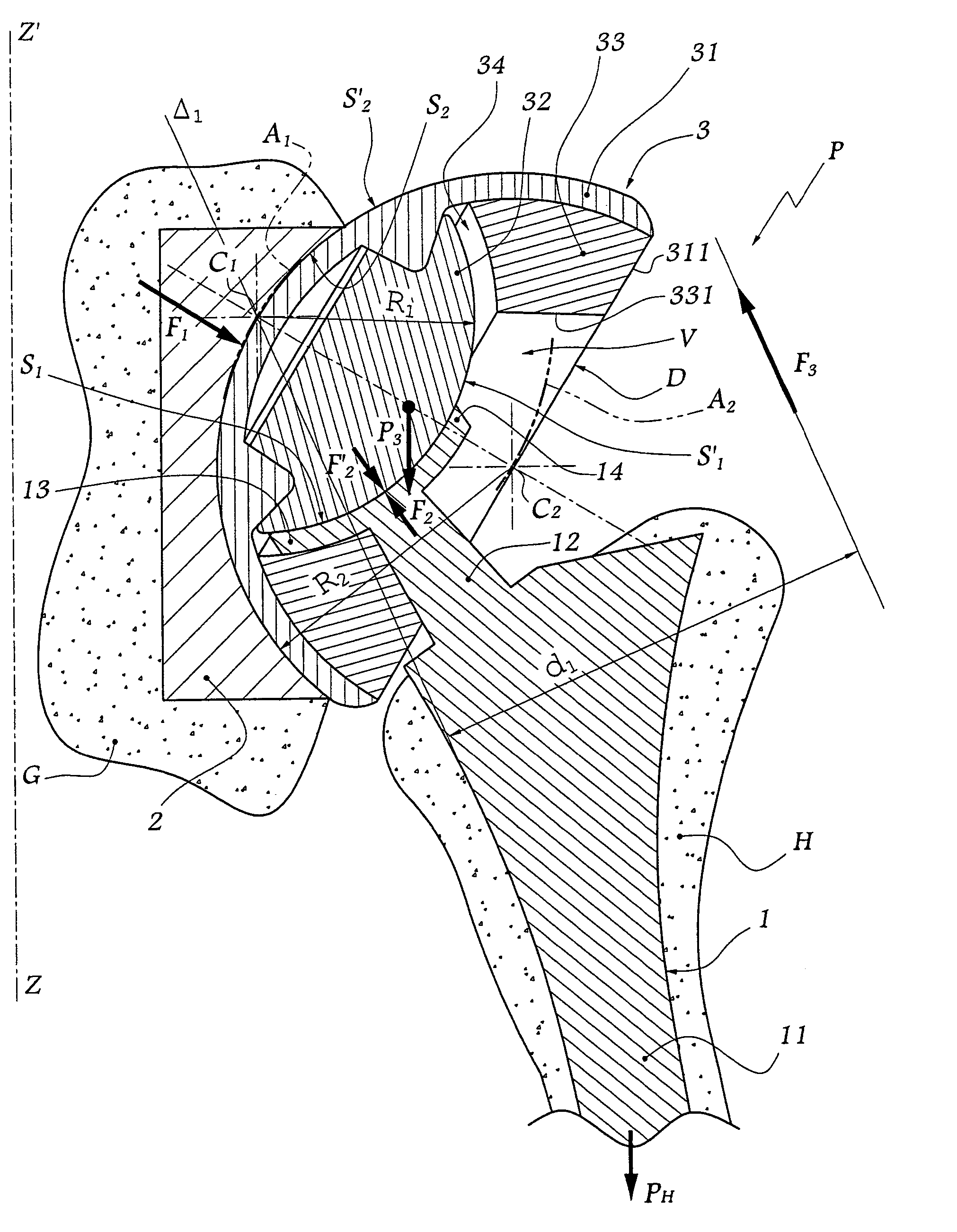
[0048]In the second form of embodiment of the invention shown in FIG. 6, the components 1 and 2 are respectively intended to be anchored in the femur F and the hip bone I. They are similar to those described with reference to the The intermediate component 3 differs from the preceding one in that it has a substantially bi-convex shape with a first surface S′2 in the form of portions of sphere of which C1 denotes the geometrical centre and a second surface S′2, likewise in the form of portions of sphere, of which C2 denotes the geometrical centre. The centres C1 and C2 are the instantaneous centres of rotation during the movements of slide of the plate 13 of the component 1 with respect to the component 3 and of the component 3 with respect to the component 2.

[0049]In practice, forces of friction (not shown) must be overcome during the movements of the humerus H or of the femur F. These forces have low values with respect to the efforts mentioned above, which makes it possible to di...

third embodiment

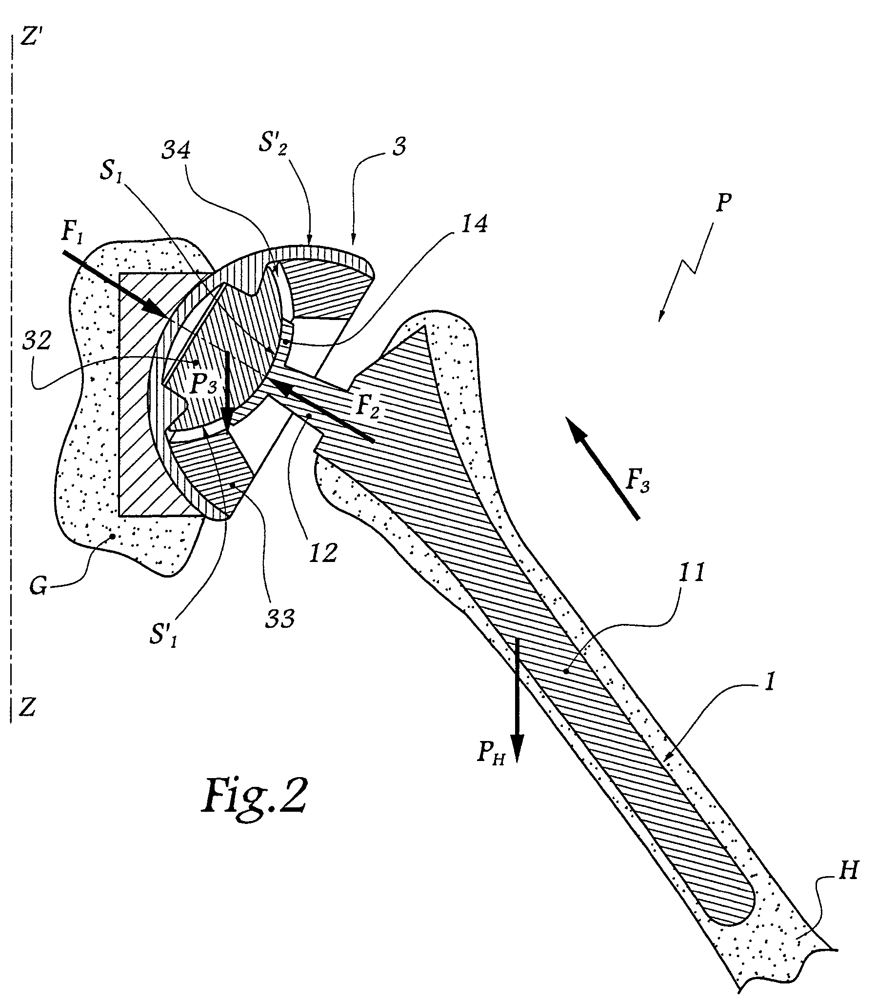
[0058]In the fourth form of embodiment of the invention shown in FIGS. 10 and 11, the components 1 and 2 are respectively intended to be anchored in the femur and in the hip bone. The intermediate component 3 is similar to that of the third embodiment and the convex surfaces S′1 and S′2 that it defines induce the same positioning of their instantaneous centres of rotation as previously.

[0059]This embodiment differs from the preceding one in that the assembly between the femoral stem 15 and the finger 16 is conical. A truncated part 17 is provided on the finger 16 in order to be engaged in a housing in the stem 15.

[0060]In addition, the plate 13 which defines the concave surface SI intended to cooperate with the surface S′1 of the component 3 is of substantially rectangular shape. As in the third embodiment, the smallest dimension of the plate 13 is disposed in the plane of FIG. 10.

[0061]It will be noted that the finger 16 is not rectilinear, which makes it possible to optimalize the...


PUM


Abstract

The prosthesis of this invention comprises a humeral or femoral component presenting a concave articulation surface, and an intermediate component presenting first and second convex articulation surfaces intended to cooperate respectively with said concave articulation surface of the humeral or femoral component and with a concave glenoid or cotyloid articulation surface. The locus of the instantaneous centers of rotation of the first convex articulation surface, with respect to the concave humeral or femoral articulation surface, and the locus of the instantaneous centers of rotation of the second convex articulation surface on the glenoid or cotyloid surface, are located on either side of the first surface.

Description

BACKGROUND OF THE INVENTION[0001]1. Field of the Invention[0002]The present invention relates to a complete or partial shoulder or hip prosthesis making it possible to reproduce, with an improved degree of precision, the characteristics of a natural joint.[0003]2. Description of the Related Art[0004]In the domain of shoulder prostheses, it is known, for example from European Patent Application 0 299 889, to create a convex articular surface on a glenoid component, while a concave articular surface of corresponding shape is formed on a humeral component. The glenoid component of such a surface is very invasive and a subacromial conflict of the humeral component may occur at the end of a movement of abduction.[0005]Furthermore, U.S. Pat. No. 4,846,840 discloses producing, on an intermediate element of a prosthesis, two substantially concentric convex surfaces with a view to their articulation on concave surfaces of corresponding shapes, provided respectively on two bones to be articul...

Claims


Application Information

Patent Timeline
IPC IPC(8): A61F2/40A61F2/00A61F2/30A61F2/32A61F2/34A61F2/36
CPCA61F2/32A61F2/40A61F2220/005A61F2/3601A61F2/3662A61F2/4059A61F2/4081A61F2002/30332A61F2002/30378A61F2002/3038A61F2002/3039A61F2002/30448A61F2002/30495A61F2002/30574A61F2002/30604A61F2002/30642A61F2002/30649A61F2002/30662A61F2002/3625A61F2002/3631A61F2002/3652A61F2002/4029A61F2002/4044A61F2220/0025A61F2220/0033A61F2/34A61F2002/30331
Inventor TORNIER, ALAIN
Owner TORNIER SA SAINT ISMIER
Why Eureka
Try Eureka