
Portable electronic instrument including at least one control member arranged for also transmitting electric signals

a technology of electronic instruments and control members, applied in the direction of instruments, coupling device connections, horology, etc., can solve problems such as the electronic circuit of instruments

Active Publication Date: 2006-04-25
THE SWATCH GRP RES & DEVELONMENT LTD
View PDF9 Cites 77 Cited by
  • Summary
  • Abstract
  • Description
  • Claims
  • Application Information

AI Technical Summary

Benefits of technology

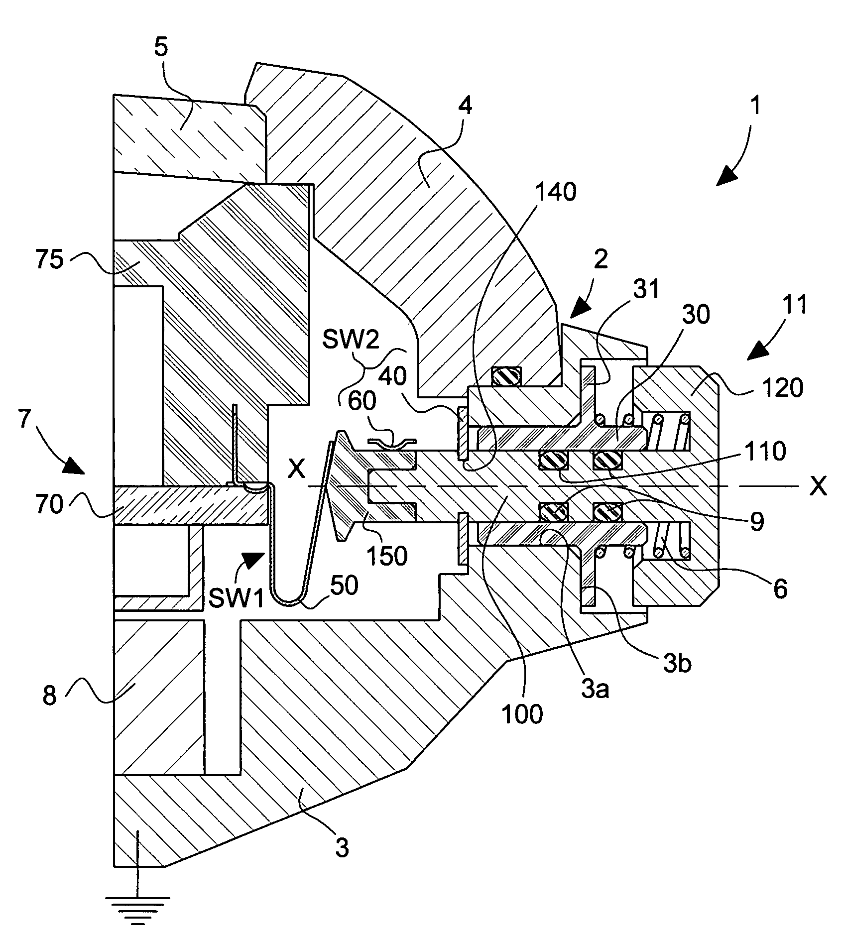
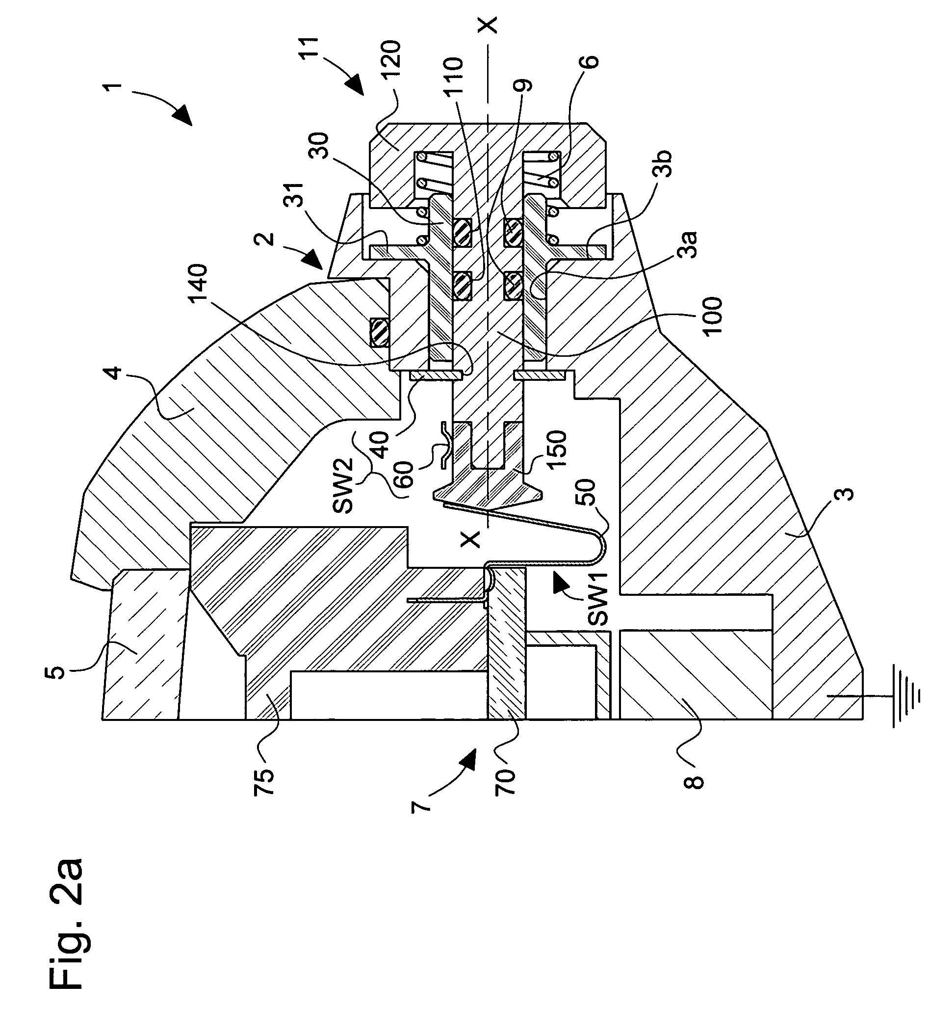
[0011]The proposed solution consists in providing means for bringing the stem of the control member to a determined electric potential when the control member occupies the non-pushed in position and for interrupting the connection of the stem of the control member to the determined electric potential when the control member occupies the pushed-in position and thus allowing transmission of electric signals from and / or to the electronic instrument.

Problems solved by technology

When the control member is actuated, this accumulation of electric charges can then be carried across the terminals with which the control member is brought into contact and cause damage, in particular to the electronic circuit of the instrument.
This constitutes a critical problem for solutions of the aforementioned type, given that the control member fulfils two functions and it establishes a direct connection with sensitive components of the electronic circuit of the instrument, in particular its processor unit and the associated memories.

Method used


Image

  • Portable electronic instrument including at least one control member arranged for also transmitting electric signals
  • Portable electronic instrument including at least one control member arranged for also transmitting electric signals
  • Portable electronic instrument including at least one control member arranged for also transmitting electric signals

Examples


Embodiment Construction

[0023]As already mentioned, the invention proceeds from the general idea that consists in connecting a portable electronic instrument (for example a wristwatch) to an external electrical or electronic device via at least one control member of the user interface with which the portable electronic instrument is fitted. “Transmission of electric signals” will cover in particular the application of electric signals for the purpose of recharging an electric accumulator with electrical energy and the communication of data to and / or from the portable electronic instrument. The external device can thus be an electrical charging device or an electronic communication device, for example a personal computer.

[0024]Within the scope of the present invention, it will be understood that the control member or members thus configured fulfil two functions, namely their first control function for selecting functions of the portable electronic instrument (selection of operating or data modes, data updat...


PUM


Abstract

There is disclosed a portable electronic instrument (1) including a case (2) and a user interface (11 to 15) for selecting the functions of said portable electronic instrument, this user interface including at least a first control member (11) mounted to be mobile in an assembly orifice (3a) arranged in the case so as to have a translation travel along an axis of actuation (X—X), said control member being able to be actuated by pressure to be brought from a position called the non pushed-in position to a position called the pushed-in position and to generate in response a control signal (SEL). The control member includes an electrically conductive stem (100) which passes through the assembly orifice and which includes first and second ends opening out respectively inside and outside the case, said stem being adapted to allow transmission of electric signals from and / or to the portable electronic instrument, when the control member is brought into said pushed-in position. This electronic instrument further includes means (3, 30, 40; 35, 40) for bringing the stem of the control member to a determined electric potential when the control member occupies the non pushed-in position and for interrupting the connection of the stem of the control member to the determined electric potential when the control member occupies said pushed-in position and for thus allowing transmission of said electric signals from and / or to the portable electronic instrument.

Description

[0001]This application claims priority from European Patent Application No. 03010126.5 filed Sep. 23, 2003, the entire disclosure of which is incorporated herein by reference.FIELD OF THE INVENTION[0002]The present invention concerns generally a portable electronic instrument, particularly a timepiece, including a case and a user interface for selecting the functions of the portable electronic instrument, this user interface including a least a first control member mounted so as to be mobile in an assembly orifice arranged in the case so as to have a translation travel along an axis of actuation, this control member being able to be actuated by pressure to be brought from a position called the non-pushed in position to a position called the pushed-in position and to generate in response a control signal, the control member including an electrically conductive stem which passes through the assembly orifice and which includes first and second ends opening out respectively inside and o...

Claims


Application Information

Patent Timeline
Patent Type & Authority Patents(United States)
IPC IPC(8): H01H3/12G04G21/00G04G99/00H01H13/02H01H13/52H01R13/648
CPCH01R13/6485G04G99/00
Inventor FERRI, YVANDINGER, RUDOLF
Owner THE SWATCH GRP RES & DEVELONMENT LTD
Learn More