Arc chute and circuit interrupter employing the same

a circuit breaker and chute technology, applied in the field of circuit breakers, can solve the problems of damage to the housing of the arc chamber, damage to the moveable and stationary contacts, and undesirable arcs

Active Publication Date: 2006-04-25
EATON INTELLIGENT POWER LIMITED
View PDF23 Cites 78 Cited by
  • Summary
  • Abstract
  • Description
  • Claims
  • Application Information

AI Technical Summary

Benefits of technology

[0029]The exit portion may be a top portion. The first and second edges of the arc plates may be top and bottom edges, respectively. The first and second edges of the insulating dividing members may be top and bottom edges, respectively. The insulating dividing members may extend above the top edge of the arc plates and overlap the arc plates, in order to prevent an arc from the stationary contact and the movable contact, when opened by the operating mechanism, from reachin

Problems solved by technology

Such an arc is undesirable for a number of reasons.
Additionally, the electrical arc extending between the contacts often results in vaporization or sublimation of the contact material itself, eventually resulting in destruction or pitting of the moveable and stationary contacts.
Low voltage air circuit breakers interrupting relatively high currents (e.g., 100,000 A and higher) with molded housings and enclosed arc chambers may often sustain damage to their housings during short circuit interruption.
Arcing energy at the corresponding power levels produces a pressure wave that may crack molded composite parts and collapse sheet-metal plates.
Corresp

Method used


Image

  • Arc chute and circuit interrupter employing the same
  • Arc chute and circuit interrupter employing the same
  • Arc chute and circuit interrupter employing the same

Examples


example 1

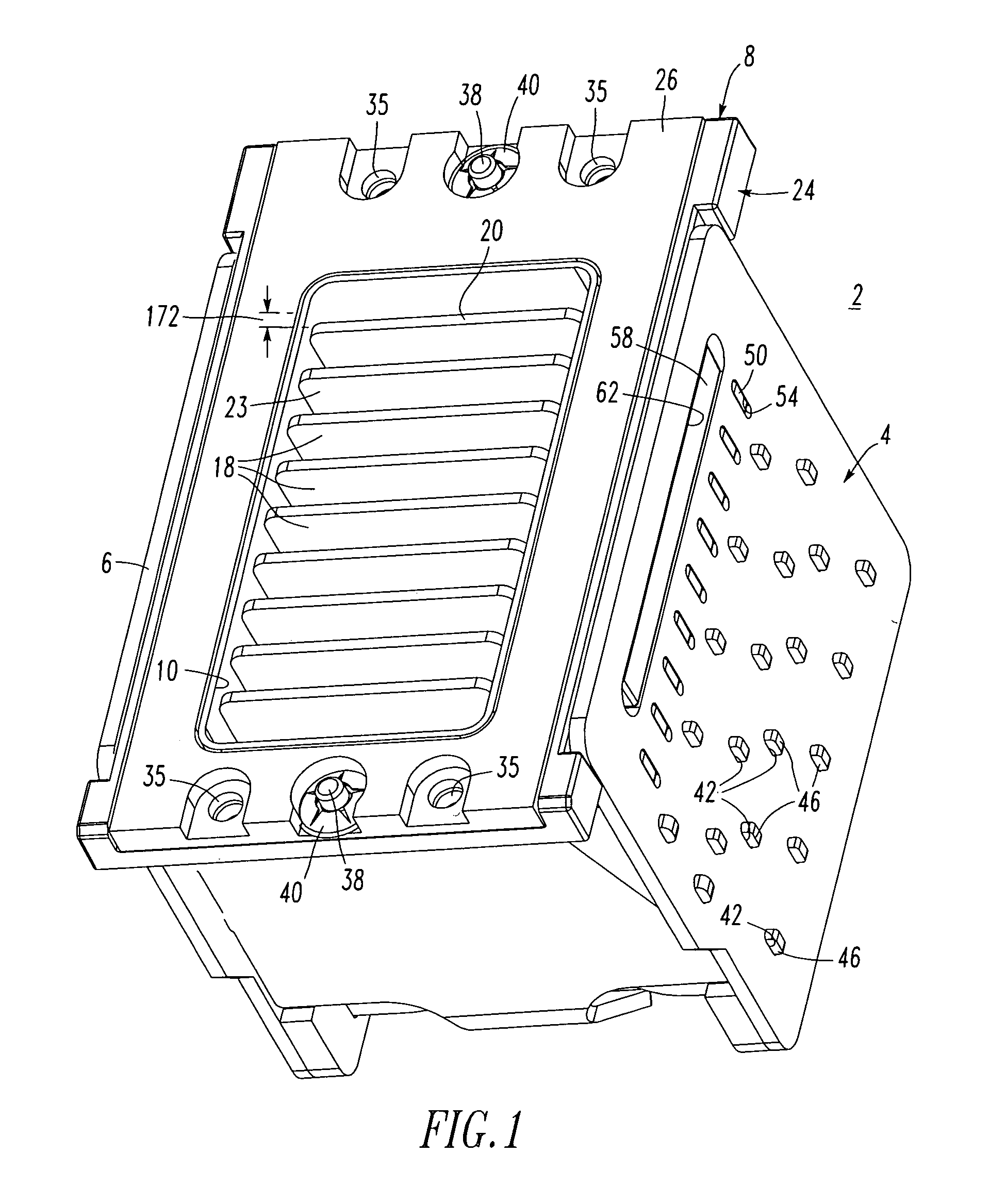
[0053]Although not shown in FIG. 1, the surfaces 63 of the baffles 18 may interlock with the notches 65 on the bottom side of the molded top 24, in order to provide added mechanical support and to prevent arc bypass.

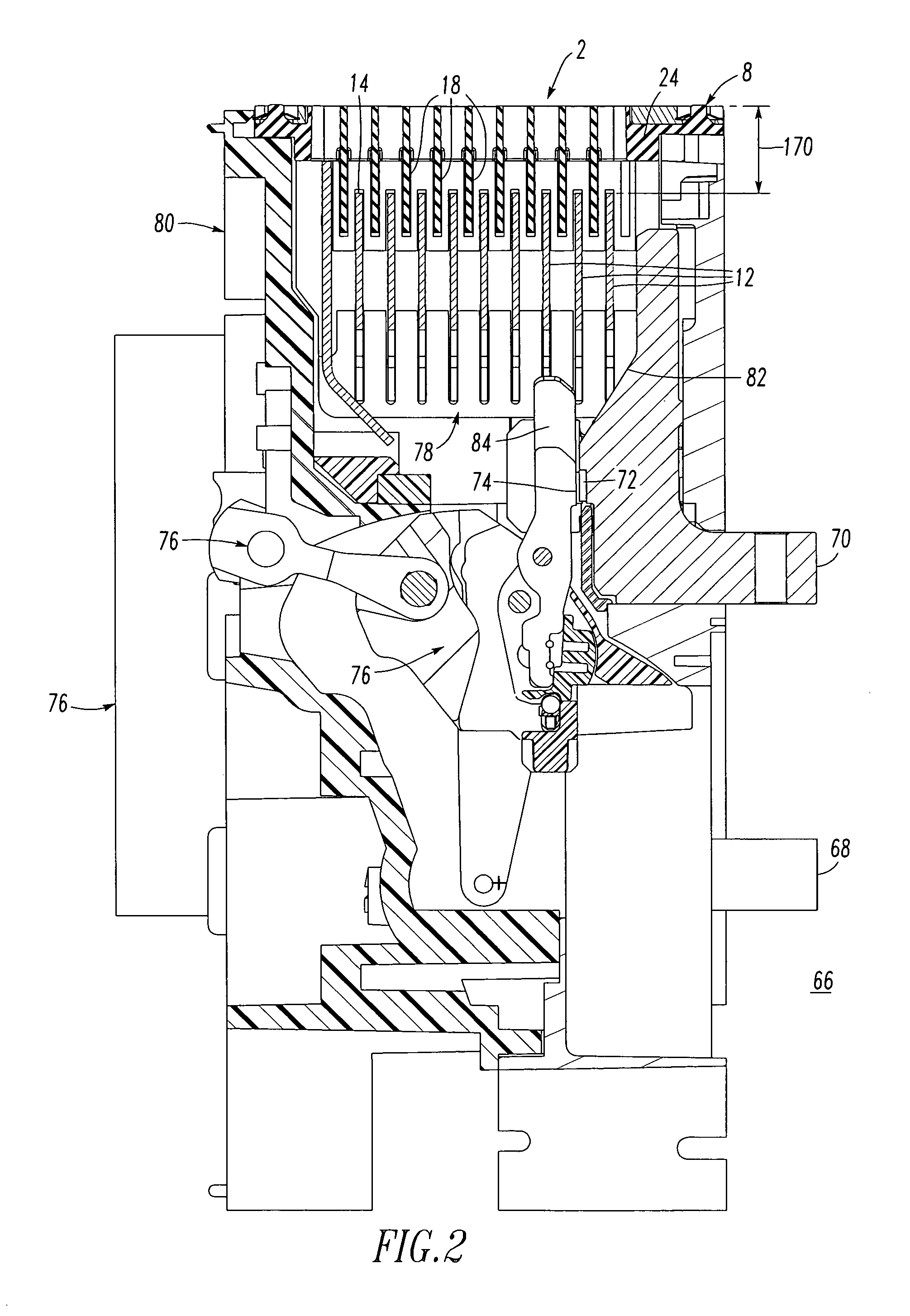
[0054]FIG. 2 shows a circuit breaker 66 incorporating the arc chute 2 of FIGS. 1 and 15. The circuit breaker 66 includes a first power terminal 68, a second power terminal 70, a stationary contact 72 electrically connected to the second power terminal 70, a movable contact 74 electrically connected by a suitable flexible (e.g., braided) conductor (not shown) to the first power terminal 68, an operating mechanism 76 adapted to open and closed the contacts 72,74; and the arc chute 2. Each one of the baffles 18 is disposed between and is separated from an adjacent pair of the arc plates 12. As best shown in FIG. 2, the baffles 18 extend above the top edge 14 of the arc plates 12 and overlap such arc plates, in order to prevent an arc from the stationary contact 72 and the m...

example 2

[0058]Although relatively thicker metal arc plates 12 may be employed to reduce bending, in the event that two or more arc plates 12 bend toward each other, the insulating dividing baffle 18 between them prevents contact, and thereby maintains the effective cooling surface area and number of voltage divisions in the arc chute 2.

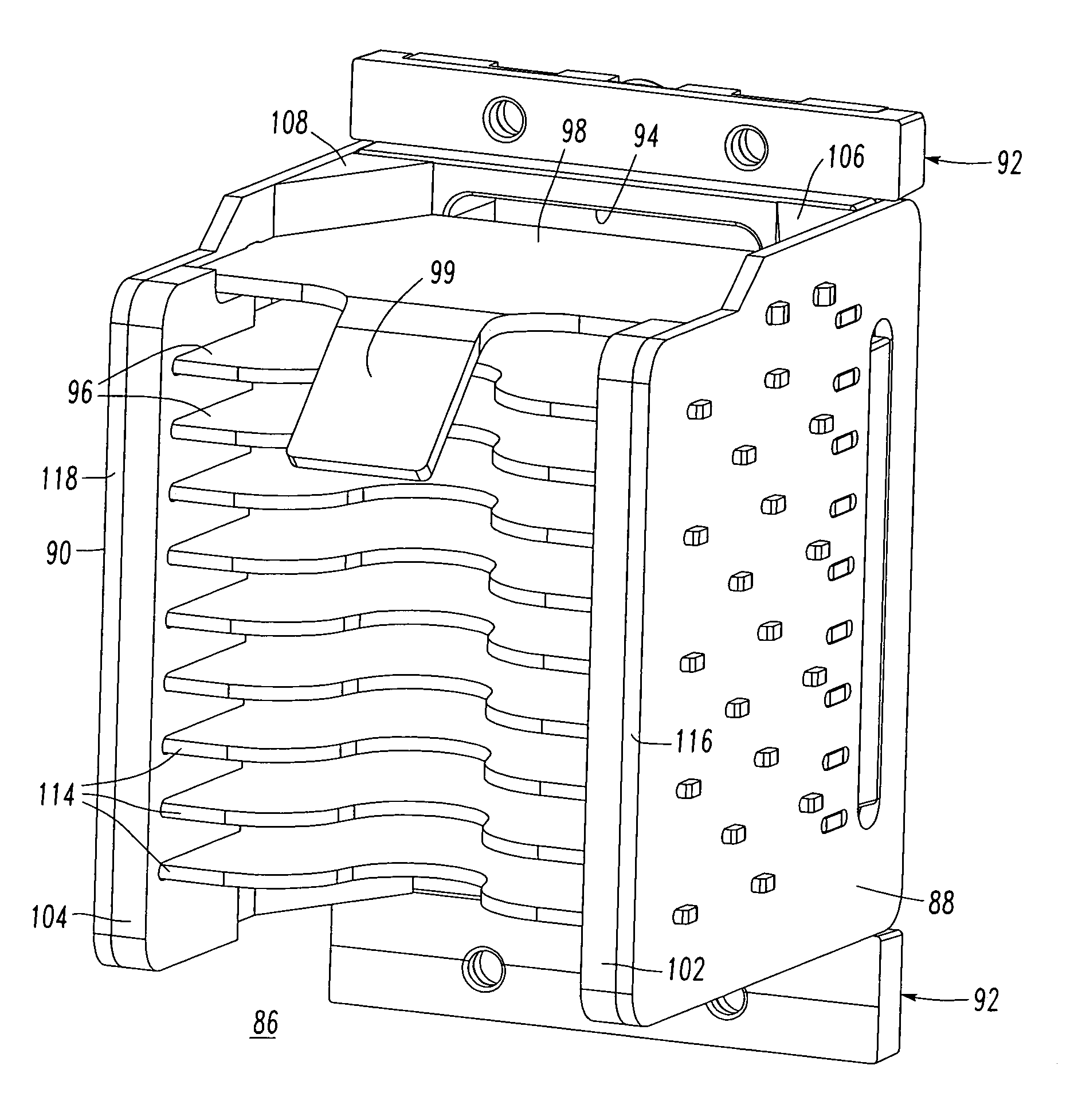
[0059]FIG. 3 shows another arc chute 86 that is somewhat similar to the arc chute 2 of FIG. 1. The arc chute 86 includes a first support or side portion 88, a second support or side portion 90, an exit or top portion 92, a vent opening 94, a plurality of generally parallel electrically conductive arc plates 96 including a top arc plate 98 having an arc horn 99, and a plurality of insulating dividing members, such as baffles 100. The arc chute 86 further includes a pair of gassing combs 102,104 (as best shown in FIG. 13) and a pair of arc chute gas diverting wedges 106,108 (as best shown in FIGS. 6 and 14) (e.g., without limitation, made of a suitable insulati...

example 3

[0065]The difference in the widths 150,152 may be, for example, 0.1 inch. This difference provides a gap that doubles the leading edge plate spacing, thereby making it easier for an arc, if formed on the outer contact arms, to enter the arc plates 12. A larger arc plate spacing provides less resistance to arc motion than tightly spaced arc plates. Otherwise, the arc might “stall” at the leading edge and track on the surface.

[0066]FIGS. 9–12 show other molded arc chute tops 154,156,158,160, which are somewhat similar to the molded top 24 of FIG. 8. Here, instead of the single vent opening 28 of FIG. 8, there are a plurality of vent openings 162,164,166,168 in the respective molded tops 154,156,158,160. In these examples, the top edge 14 of the arc plates 12 (FIG. 2) is offset below the vent openings 162,164,166,168 by a first distance 170 (FIG. 2), while the top edge 20 of the insulating dividing members 18 (FIG. 1) is offset below the vent openings 162,164,166,168 by a second distan...


PUM


Abstract

A circuit interrupter arc chute includes first and second support portions, an exit portion supported by the support portions, and a plurality of arc plates supported by the support portions. The exit portion has one or more vent openings. The arc plates have a first edge offset from the exit portion and an opposite second edge distal from the exit portion. A plurality of insulating dividing members are disposed between the arc plates. The members have a first edge proximate the exit portion and an opposite second edge distal from the exit portion. The second edge of the members extends beyond the arc plate first edges and toward the arc plate second edges. The first edge of the dividing members extends beyond the arc plate first edge and away from the arc plate second edge.

Description

BACKGROUND OF THE INVENTION[0001]1. Field of the Invention[0002]This invention pertains generally to circuit interrupters and, more particularly, to arc chutes for circuit breakers.[0003]2. Background Information[0004]Circuit breakers typically include a set of stationary electrical contacts and a set of moveable electrical contacts. The stationary and moveable contacts are in physical contact with one another when it is desired that the circuit breaker provide electricity therethrough to a load. When it is desired to interrupt the circuit, however, the moveable contacts are moved away from the stationary contacts, thus removing the moveable contacts from physical contact with the stationary contacts and creating a space therebetween.[0005]The movement of the moveable contacts away from the stationary contacts results in the formation of an electrical arc in the space between the contacts beginning at the time the contacts are initially separated. Such an arc is undesirable for a nu...

Claims


Application Information

Patent Timeline
IPC IPC(8): H01H33/02
CPCH01H9/362H01H73/18H01H9/342H01H2009/347H01H9/46H01H9/302
Inventor SHEA, JOHN J.RAKUS, PAUL R.PENDRICK, THOMAS C.MARCHAND, FRANCOIS J.SISSON, GLEN C.
Owner EATON INTELLIGENT POWER LIMITED
Why Eureka
Try Eureka