
Radial-axial electromagnetic flux electric motor, coaxial electromagnetic flux electric motor, and rotor for same

a technology of electric motors and rotors, applied in the direction of synchronous motors, magnetic circuit rotating parts, magnetic circuits, etc., can solve the problems of low power efficiency, high power density machines such as dc machines and permanent magnet synchronous machines (pmsms), and other windings are not able to operate in a normal manner, so as to achieve the effect of increasing power outpu

Inactive Publication Date: 2006-04-25
REGAL BELOIT AMERICA +1
View PDF12 Cites 55 Cited by
  • Summary
  • Abstract
  • Description
  • Claims
  • Application Information

AI Technical Summary

Benefits of technology

[0016]The invention provides numerous high power density machines that offer high reliability, by comparison to related art machines. These features are achieved by using two stators instead of one, as in related art architectures. The use of multiple stators increases the stator-dependent reliability of the architecture. Also, the invention uses the same rotor to combine both axial and radial field motors, even though the stators are in the radial and axial directions, respectively.
[0019]Still another object of the invention is to provide a high power density electrical machine having high reliability.
[0021]A further object of the invention is to provide an electrical machine that increases the power output for a given volume of space taken by the motor.

Problems solved by technology

Usually, related art high power density machines, such as permanent magnet synchronous machines (PMSMs) and permanent magnet brushless direct current (dc) machines (PMBDCMs), are not capable of providing high reliability under all operating conditions.
As a result, these other windings are not able to operate in a normal manner, since they may require higher than nominal voltages to operate.
The short circuit will bleed power from the source and put it to waste, resulting in low power efficiency.
Therefore, such consequences are undesirable.
Since only one winding is used on the rotor to generate torque, the machine's ability to operate with a fault is low or non-existent.
Though these patents describe techniques for increasing efficiency, they do little to advance the fault tolerance of the machines.
The disclosed structure is achieved by extending the machine in the axial direction and diminishing the volume of space between the two rotor shafts, thus significantly reducing the power density of the machine.
Also, a fault occurring in the stator winding prevents power from being applied to either rotor shaft.
These shortcomings limit the applications to which this machine may be applied.
The disadvantage of this motor architecture is that it increases the rotor inertia, which is proportional to the fourth power of the diameter.
Also, this architecture does not advance the art in terms of arranging the relative placement of the motors, arranging the stator windings of the motors, and the magnetic arrangement of the rotors.

Method used


Image

  • Radial-axial electromagnetic flux electric motor, coaxial electromagnetic flux electric motor, and rotor for same
  • Radial-axial electromagnetic flux electric motor, coaxial electromagnetic flux electric motor, and rotor for same
  • Radial-axial electromagnetic flux electric motor, coaxial electromagnetic flux electric motor, and rotor for same

Examples


Embodiment Construction

[0042]To significantly increase the power density of an electric machine, the unutilized space of the machine must be put to use. This unutilized space may be found in the rotor and in the stator end bells. To put this space to use, without increasing the stator volume, or at least unduly so, an axial-flux switched reluctance machine (SRM) motor may be disposed on a regular, radial-flux SRM motor. Axial flux flows in the axial direction of the machine and an axial field produces this flow. Under the influence of a radial field, a radial flux flows along a radius of the machine's axial shaft and perpendicular to the machine's axial direction. In this way, a pair of radial and axial flux motors may share a single rotor.

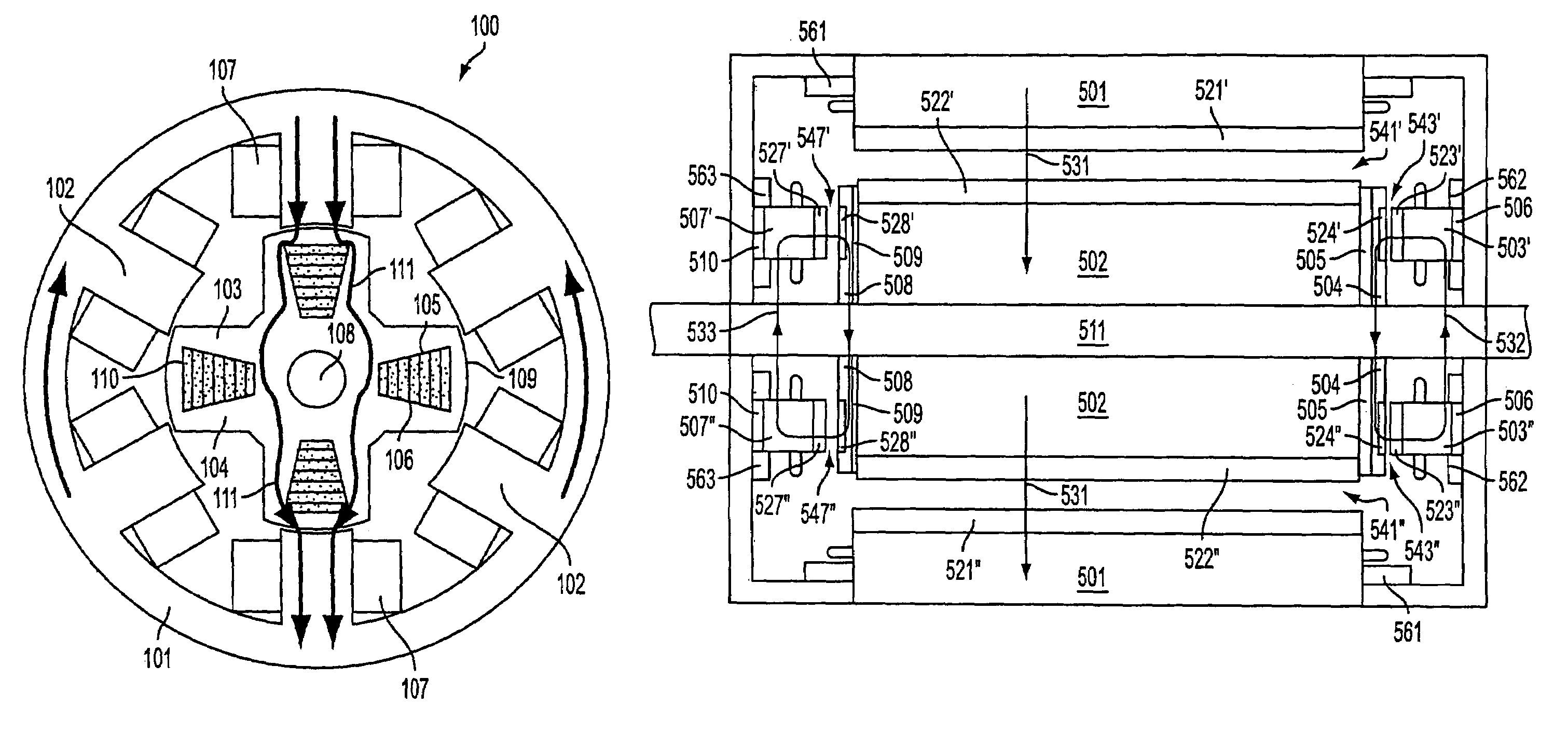
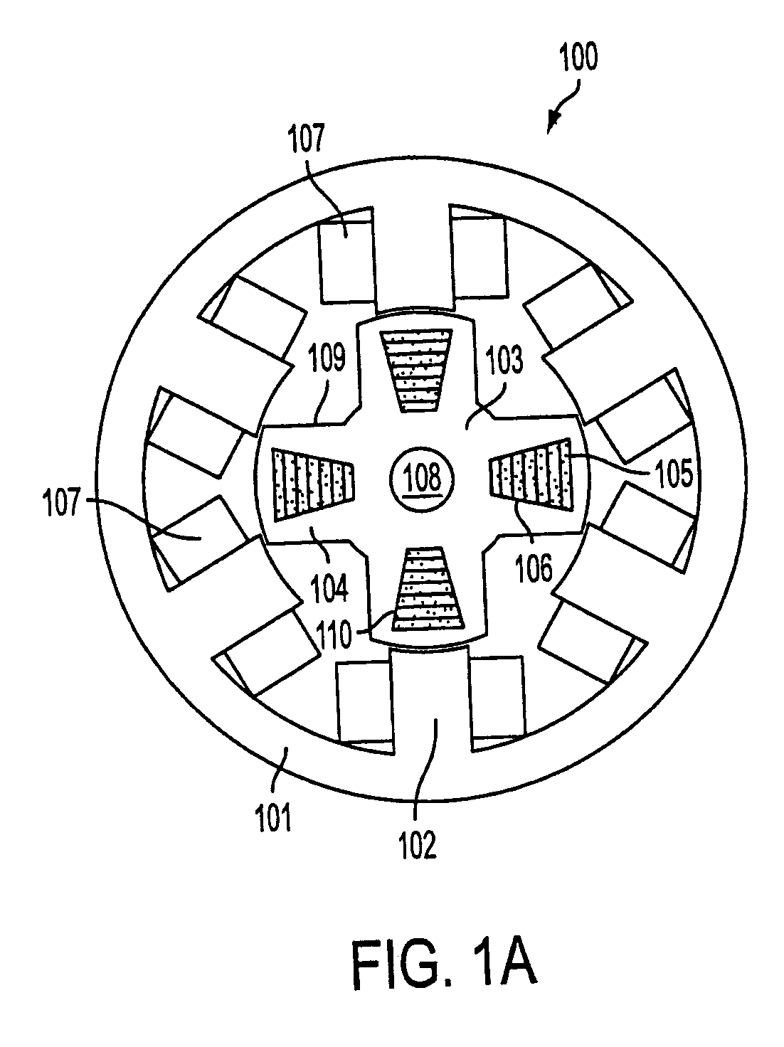
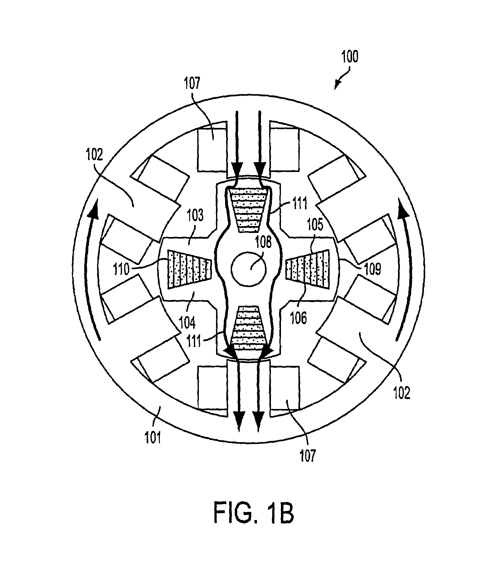
[0043]FIG. 1(a) illustrates a hybrid axial-radial machine (HARM) having axial-field rotor poles centrally disposed within radial field rotor poles of the HARM. FIG. 1(b) illustrates a radial flux path through the HARM illustrated by FIG. 1(a). HARM 100 includes a stator...


PUM


Abstract

A rotor for an electrical motor may include a plurality of salient radial field rotor poles and a plurality of salient axial field rotor poles. The radial field rotor poles and the axial field rotor poles are respectively oriented on the rotor to receive or convey substantially perpendicular flux fields. Additionally, the radial field rotor poles may include both inner and outer peripheral rotor poles for communicating radial flux fields with separate coaxial stators.

Description

[0001]This is a continuation application of PCT / US03 / 16628 filed May 27, 2003, which is based on provisional applications 60 / 382,608, 60 / 382,609, and 60 / 382,610 all filed on Nov. 24, 2002.CROSS-REFERENCE TO RELATED APPLICATIONS[0002]This application claims priority to Provisional Application Nos. 60 / 382,608, 60 / 382,609, and 60 / 382,610. Additionally, the application hereby incorporates by reference the disclosures provided in Applicant's co-pending PCT International applications filed on the same date herewith, having Attorney Docket Nos. L1081.03101, L1081.03102, L1081.03103, and L1081.03105 and filed herewith.BACKGROUND OF THE INVENTION[0003]1. Field of the Invention[0004]The invention relates to radial-axial electromagnetic flux electric motors, coaxial electromagnetic flux electric motors, and rotors for a radial-axial electric motor.[0005]2. Description of Related Art[0006]Many high performance applications, such as electric actuators in aircraft and variable speed motor drives ...

Claims


Application Information

Patent Timeline
Patent Type & Authority Patents(United States)
IPC IPC(8): H02K33/12H02K1/24H02K16/04H02K7/09H02K19/10H02K21/12
CPCH02K1/246H02K21/12H02K19/103H02K7/09H02K16/04
Inventor RAMU, KRISHNAN
Owner REGAL BELOIT AMERICA
Learn More