Data converter

Inactive Publication Date: 2006-04-25
KONINKLIJKE PHILIPS ELECTRONICS NV
View PDF5 Cites 0 Cited by
  • Summary
  • Abstract
  • Description
  • Claims
  • Application Information

AI Technical Summary

Benefits of technology

[0009]A preferred embodiment of the data converter according to the present invention is characterized in that the transfer function of the discrete-time low-pass filter comprises, in its complex z-plane, a plurality of poles at or close to the point (1;0) of the unit circle of said plane and an additional pole on the positive real axis of said plane at a value between 0.20 and 0.92 for decreasing the idle oscillation frequency of the sigma delta modulator. Said plurality of poles may be positioned in known manner so that a suitable low frequency pass band, e.g. with Butterworth or Chebyshev characteristic, and a sufficiently steep roll off is obtained. These poles operate mainly in the baseband of the signals to be converted and substantially contribute to the noise shaping, i.e. the reduction of the noise power in said baseband. The additional pole on the real axis is mainly operative in the higher frequency band and determines the average frequency at which the loop will oscillate i.e. the average length of the pulse patterns. In the example given below this pole is positioned at the point (0.88;0) of the complex z-plane. Positioning the additional pole further away from the point (1;0) would increase the oscillator frequency, i.e. the more the additional pole is away from the point (1;0) the less influence the pole has on the pulse pattern. If it is desired to further decrease the oscillator frequency the pole has to be positioned closer to the point (1;0), however any further shift beyond approximately 0.92 would bring the pole too close to the point (1;0) and would cause the pole to lose any control over the oscillation pattern.
[0010]Preferably the DA-converter of the present invention is further characterized in that the transfer function of the discrete-time low-pass filter has a number of poles that exceeds the number of zeroes of said discrete-time low-pass filter by at least 2. Because usually in a digital sigma delta modulator the number of poles exceeds the number of zeroes by one, this means that the additional pole is introduced without the introduction of an additional zero. The position of the zeroes is a compromise between the stability requirements and the noise shaping requirements of the sigma

Problems solved by technology

If it is desired to further decrease the oscillator frequency the pole has to be positioned closer to the point (1;0), however any further shift be

Method used


Image

  • Data converter
  • Data converter
  • Data converter

Examples


Embodiment Construction

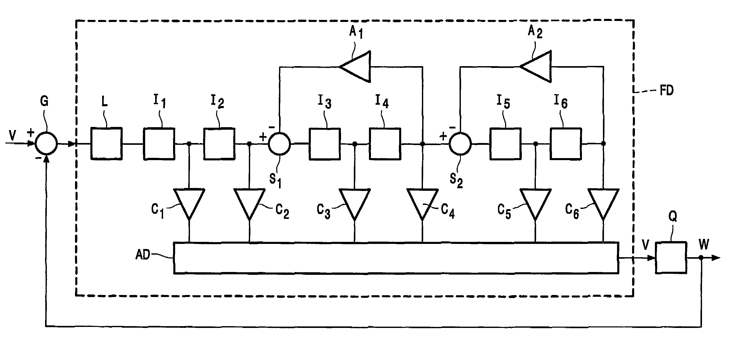
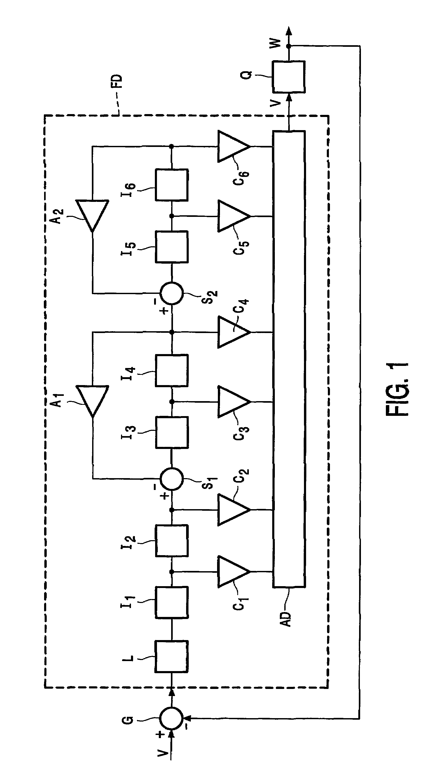
[0017]The data converter of FIG. 1 comprises a digital low-pass filter FD that receives at its input terminal a digital input signal U, e.g. a digital PCM-signal, through a comparator G that might be a simple subtracter. The output signal V of the digital low-pass filter is quantized in a one-bit quantizer Q and the output W of the quantizer is fed back to the comparator G. Therefore, the comparator subtracts the quantizer output W from the input signal U, the difference signal U-W is passed to the digital low-pass filter FD and the low-frequency content of this difference signal U-W is applied to the quantizer. The output of the quantizer is a series of single-bit pulses, which may, with respect to a reference value, have either +1 or −1 value. The structure of comparator G, digital low-pass filter FD and quantizer Q constitutes a discrete-time sigma delta modulator which keeps the difference between the value of the PCM input signal and the low frequency content of the pulses W as...


PUM


Abstract

A data converter comprises a discrete-time sigma delta modulator e.g. for driving a Class-D power amplifier. The low-pass filter of the sigma delta modulator is modified by adding a suitably positioned pole to lower the oscillation frequency (limit cycle) of the sigma delta modulator in order to obtain increased clustering of the pulses applied to the output of the data converter.

Description

CROSS-REFERENCE TO RELATED APPLICATION[0001]This application is a 371 of PCT / IB03 / 04220 filed on Sep. 22, 2003.FIELD OF INVENTION AND RELATED ART[0002]The invention relates to a data converter comprising a sigma delta modulator intended to operate at a specific sample frequency, said sigma delta modulator comprising in a feedback loop a comparator, a discrete-time low-pass filter and a quantizer in that order, in which the comparator is arranged to compare the output of the quantizer with the input signal to be converted. Such data converter is known from the article “Digital Power Amplification Using Sigma-Delta Modulation and Bit Flipping” by A. J. Margrath and M. B. Sandler in J. Audio Engineering Society, Vol. 45, No 6, pp 476–487, June 1997.[0003]The invention is particularly but not exclusively of interest to driving switching power amplifiers (class D amplifiers). These amplifiers are used for instance in motor drivers, supply regulators and audio amplifiers. Conventional cla...

Claims


Application Information

Patent Timeline
IPC IPC(8): H03M3/00H03M7/00H03M7/32
CPCH03M7/3035H03M7/00H03M7/3002
Inventor SCHINKEL, DANIEL
Owner KONINKLIJKE PHILIPS ELECTRONICS NV
Why Eureka
Try Eureka