Mobile television receiver

a technology for television receivers and receivers, applied in the field of television receivers, can solve the problems of radio and television receivers, transmitters no longer being received at the current set frequency, and the movement of vehicles continuously changing the transmission terrain, etc., to achieve the effect of improving availability

Inactive Publication Date: 2006-04-25
AG BECKER & CO
View PDF27 Cites 34 Cited by
  • Summary
  • Abstract
  • Description
  • Claims
  • Application Information

AI Technical Summary

Benefits of technology

[0013]Therefore, there is a need for a navigation system that includes a sufficiently updated database with improved availability to provide the route search and destination directions of the navigation system.

Problems solved by technology

Mobile receiving devices, for example radio and television receivers in motor vehicles, encounter the problem that the progressive motion of the vehicle continuously changes the transmission terrain.
This can result in a transmitter no longer being received at the currently set frequency.

Method used


Image

  • Mobile television receiver
  • Mobile television receiver
  • Mobile television receiver

Examples


Embodiment Construction

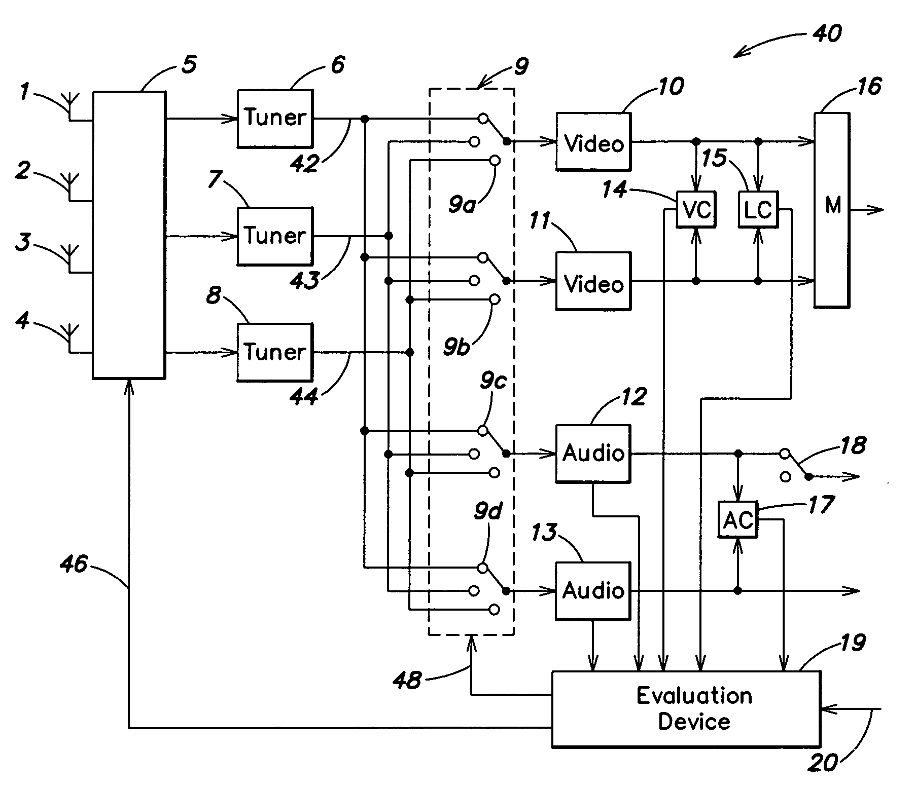
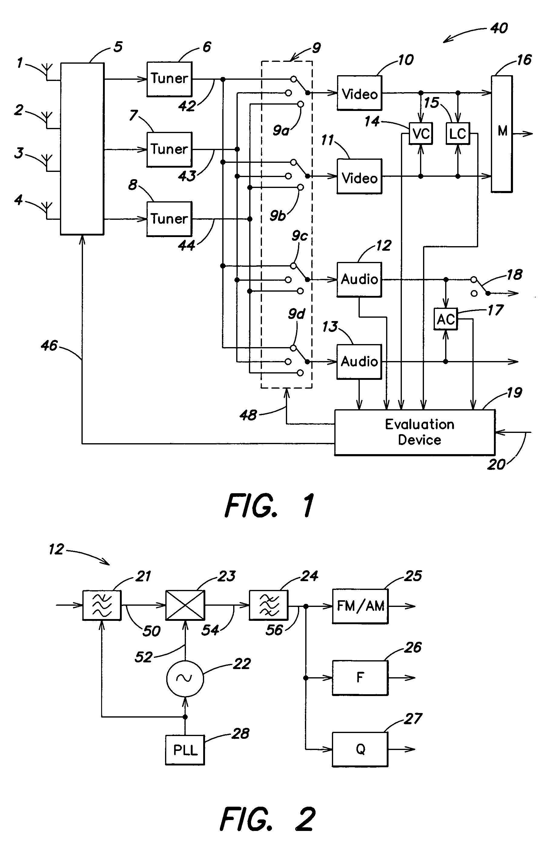
[0018]FIG. 1 is a block diagram illustration of a mobile television receiving device 40. The receiving device 40 includes a plurality of antennas 1–4 that are attached for example at different positions on a motor vehicle. Each of the antennas 1–4 provides an associated received signal to a high-frequency switching device 5, which switches the received signals to a plurality of television channel selection devices 6–8. The switching device 5 can route any one of the received signals provided by the antennas to any one of channel selection devices 6–8. For example, the signal from antenna 1 may be provided to channel selection device 8, the signal from antenna 2 may be provided to the selection device 6, while the signal from the antenna 3 may be provided to the selection device 7. The channel selection devices 6–8 each include a mixer (not shown) that converts the high-frequency signal from the particular switched-in receiving antenna 1–4 into an intermediate frequency (IF) signal b...


PUM


Abstract

The receiving device contains at least two television channel selection devices to convert high-frequency signals into intermediate-frequency signals, at least two video demodulation devices to convert the intermediate-frequency signals into picture signals, at least two audio demodulation devices to convert the intermediate-frequency signals into audio signals, and one intermediate-frequency switching device to switch the audio- and video-demodulation devices to the television channel selection devices.

Description

BACKGROUND OF THE INVENTION[0001]The invention relates to television receivers, and in particular to a mobile television receiver for motor vehicles.[0002]Mobile receiving devices, for example radio and television receivers in motor vehicles, encounter the problem that the progressive motion of the vehicle continuously changes the transmission terrain. This can result in a transmitter no longer being received at the currently set frequency. However, the transmitter generally is also available on at least at one other frequency, and thus by switching the receiving device to this frequency (preferably automatically) the transmitter can continue to be heard and seen. However, to switch to an alternative frequency in general, and in particular to switch to this frequency quickly, the alternative frequency must be detected quickly and reliably.[0003]Therefore, there is a need for a mobile television receiver for quickly and easily automatically searching through and tuning in alternative...

Claims


Application Information

Patent Timeline
Patent Type & Authority Patents(United States)
IPC IPC(8): H04N5/44H04B7/08
CPCH04N5/44H04B7/082H04N21/41422H04N21/4263H04N21/4384
Inventor ZAHM, MICHAELKOEHLER, STEFANGEIGER, ERICH A.LINK, HERMANN
Owner AG BECKER & CO
Why Eureka
Try Eureka