
3-D forward looking sonar with fixed frame of reference for navigation

a technology of forward-looking sonar and fixed frame of reference, which is applied in the field of sonar systems, can solve the problems of limiting the ability to provide upgrades and modifications, affecting the ability to provide for upgrades and modifications, and affecting the reliability of the receiver

Inactive Publication Date: 2006-04-25
FARSOUNDER
View PDF6 Cites 65 Cited by
  • Summary
  • Abstract
  • Description
  • Claims
  • Application Information

AI Technical Summary

Benefits of technology

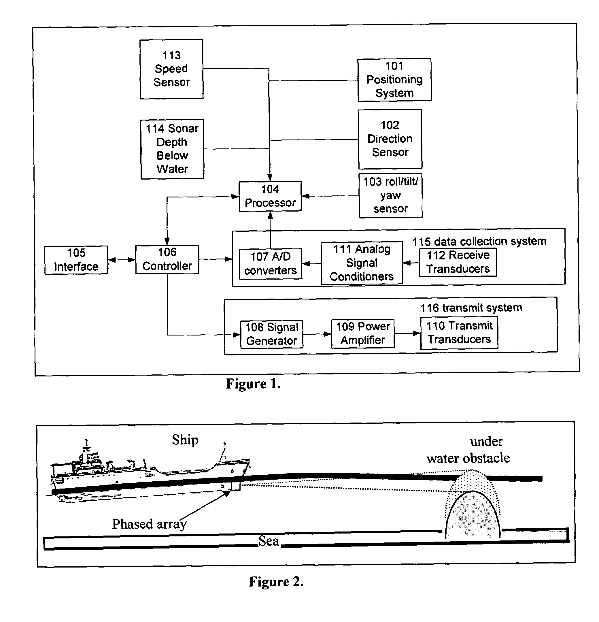
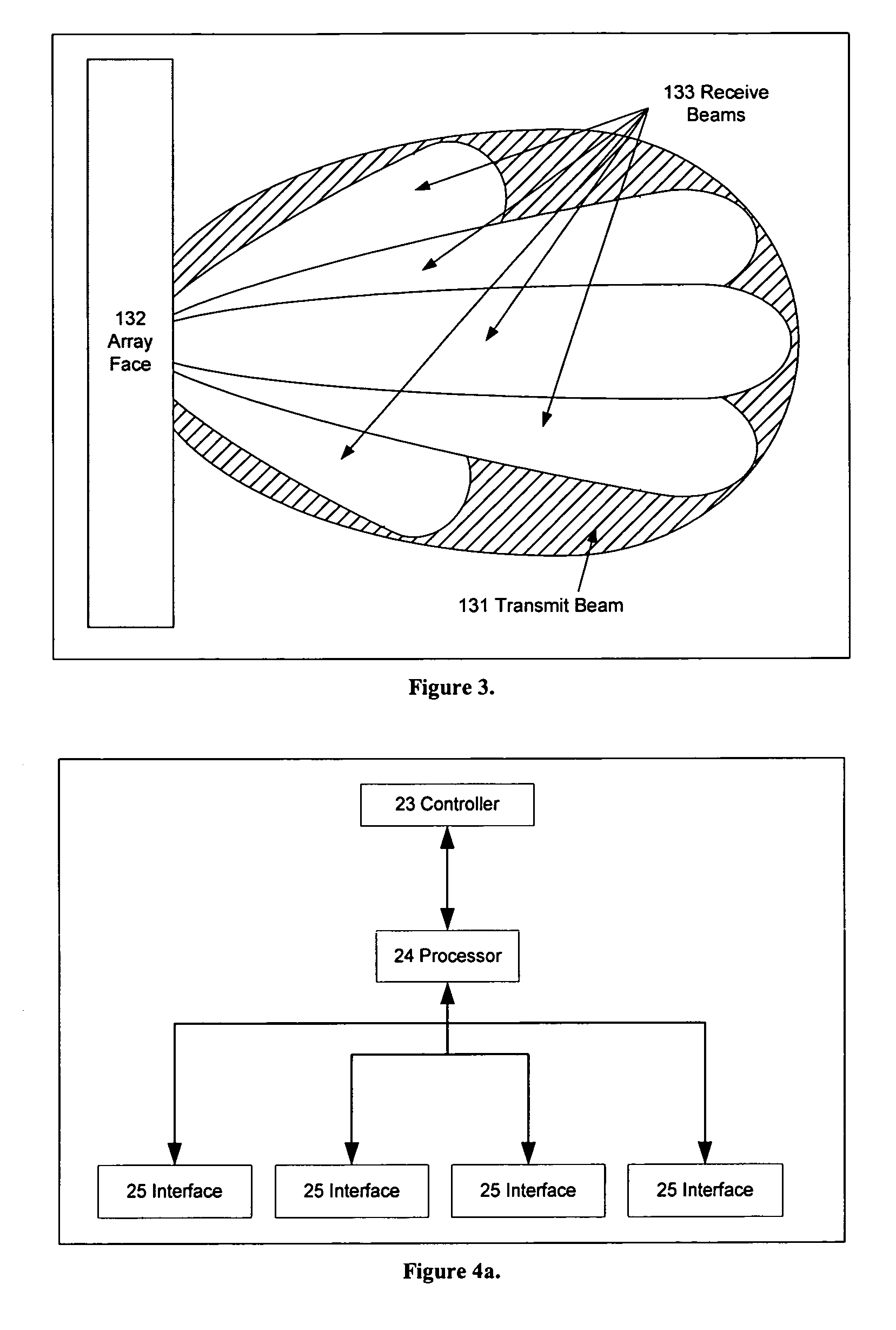
[0005]A forward looking (side looking, or bottom looking) sonar system has the following features. A transmit transducer projects a signal into the water ahead of the vessel. A phased array of receiving sensors provides signals to a computer which determines the azimuthal and elevation angles of arrival and time of arrival. This sonar is equipped with tilt and roll sensors and may be interfaced with GPS and a compass. The acoustic information along with the tilt and roll can be processed to create a 3-D image ahead of the vessel with a fixed frame of reference relative to the earth from the raw beamformed data. This is necessary in understanding the picture ahead of the vessel. By including heading and GPS sensors and information the images can be fixed to a specific location on the earth. This is necessary many displays such as historical mapping and chart overlay. Advanced signal processing techniques enable the processor to extract targets from the raw beamformed data. Additional features of the system enable the suppression of many multipath targets.

Problems solved by technology

Since the number of array elements can vary from a minimum of four to several thousand, the cost for the receiver hardware can be a real burden.
Depending on the number of array elements, this can create a serious wiring burden.
The complexity of these systems limit the ability to provide for upgrades and modifications and render repairs expensive.
Depending on their size and sea conditions, ships can tilt and roll so much that the depths of obstacles including the seafloor detected with a phased array sonar can be tens of meters in error.

Method used


Image

  • 3-D forward looking sonar with fixed frame of reference for navigation
  • 3-D forward looking sonar with fixed frame of reference for navigation
  • 3-D forward looking sonar with fixed frame of reference for navigation

Examples


Embodiment Construction

[0019]The invention will be described in connection with certain preferred embodiments, with reference to the following illustrative figures so that it may be more fully understood. With reference to the figures, it is stressed that the particulars shown are by way of example and for purposes of illustrative discussion of the preferred embodiments of the present invention only, and are presented in the cause of providing what is believed to be the most useful and readily understood description of the principles and conceptual aspects of the invention. In this regard, no attempt is made to show structural details of the invention in more detail than is necessary for a fundamental understanding of the invention, the description taken with the drawings making apparent to those skilled in the art how the several forms of the invention may be embodied in practice.

[0020]A block diagram of the preferred embodiment of a forward looking sonar is shown in FIG. 1. A forward looking (side looki...


PUM


Abstract

An imaging sonar system develops three-dimensional images of the space below, to the sides, and forward of a ship relative to a fixed frame of reference. Various features permit the system to be used in non-military environments and make possible low cost with substantial capabilities.

Description

PRIORITY[0001]Priority is claimed to U.S. patent application Ser. No. 60 / 419,728, which was filed on Oct. 21, 2002 and Ser. No. 10 / 177,889, which was filed Oct. 22, 2002.BACKGROUND[0002]There are many types of sonar systems used for military, commercial, and recreational purposes. Generally, forward looking sonar systems are designed to build a 2 dimensional image along a single vertical or horizontal slice. More advanced systems are capable of building 3 dimensional images through a series of 2 dimensional pings pointed directly below the vessel with the direction of the 2 dimensional strip being perpendicular to the track of the vessel. This type of system is downward-looking and used for bottom mapping. At present commercial forward-looking navigation sonars in creating a 3 dimensional image from a single ping, having any array geometry are unknown.[0003]In the field of interferometry, arrays of many receivers are used, which enable a user or an autonomous system controller to ma...

Claims


Application Information

Patent Timeline
Patent Type & Authority Patents(United States)
IPC IPC(8): G01S15/89G01S7/52G01S7/527G01S7/53G01S15/42G01S15/93H04B17/00
CPCG01S7/52003G01S7/527G01S7/53G01S15/93G01S15/89G01S7/6263G01S15/42G01S7/6245
Inventor ZIMMERMAN, MATTHEW JASONMILLER, JAMES HENRY
Owner FARSOUNDER
Learn More