
Method for examining a body region of an examination object, which body region performs a periodic movement, and CT apparatus for carrying out such a method

a body region and examination object technology, applied in the field of methods for examining the body region of an examination object, can solve the problems of insufficient object length coverage, loss of sharpness in the z direction, inability to cover objects in the same direction, etc., and achieve good spatial resolution and temporal resolution

Active Publication Date: 2006-04-25
SIEMENS HEALTHCARE GMBH
View PDF7 Cites 6 Cited by
  • Summary
  • Abstract
  • Description
  • Claims
  • Application Information

AI Technical Summary

Benefits of technology

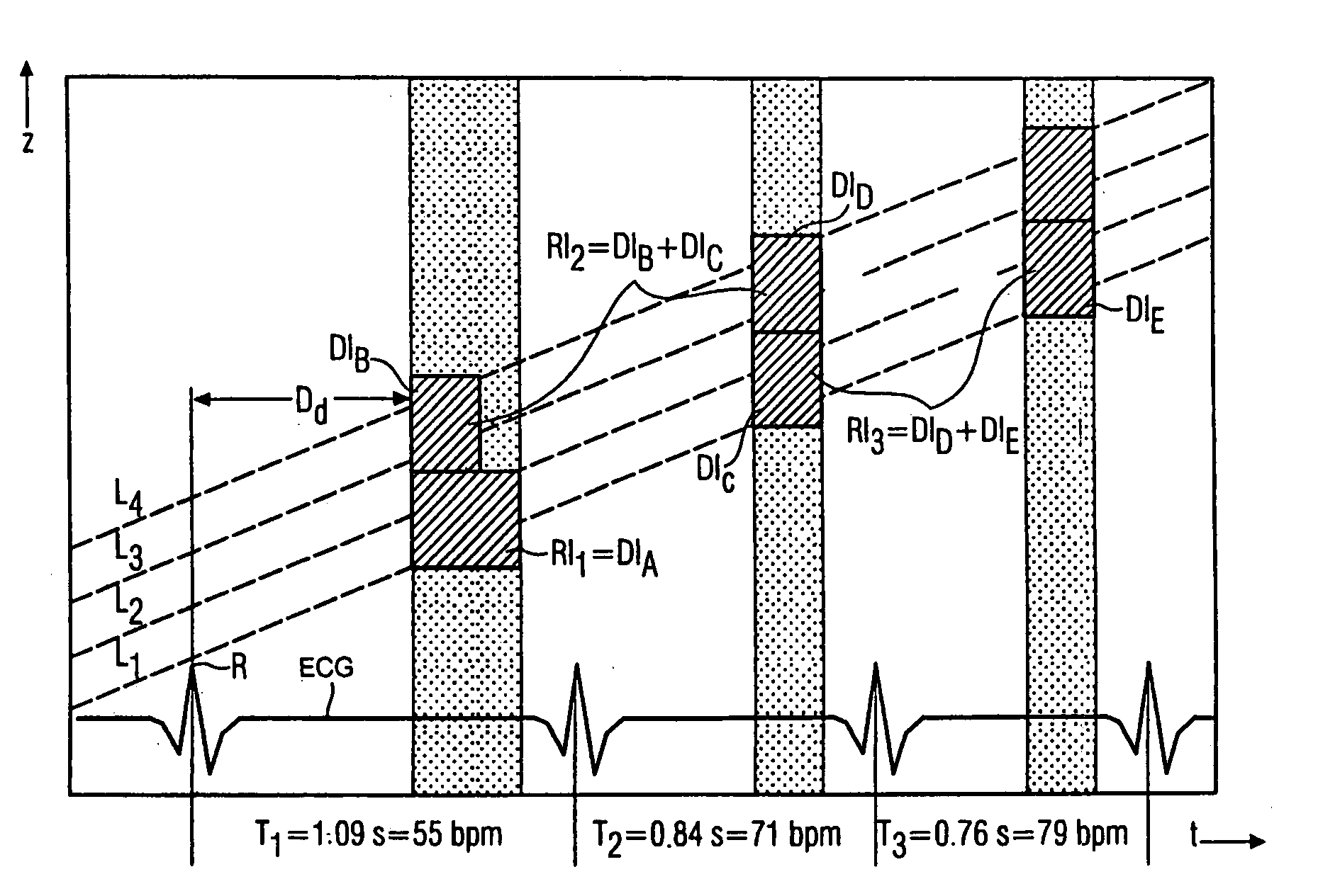
The invention is about a method and apparatus for improving the spatial and temporal resolution of computed tomography (CT) images of the heart. The method involves adapting the number of data intervals and the duration of those intervals based on the frequency of the periodic movement of the heart. By doing so, the method allows for improved spatial resolution at lower heart rates and sufficient temporal resolution at higher heart rates. The apparatus includes a CT scanner that can automatically adjust these parameters based on the heart rate during a spiral recording. The invention provides a way to image the heart with good spatial and temporal resolution while accounting for the frequency of the periodic movement.

Problems solved by technology

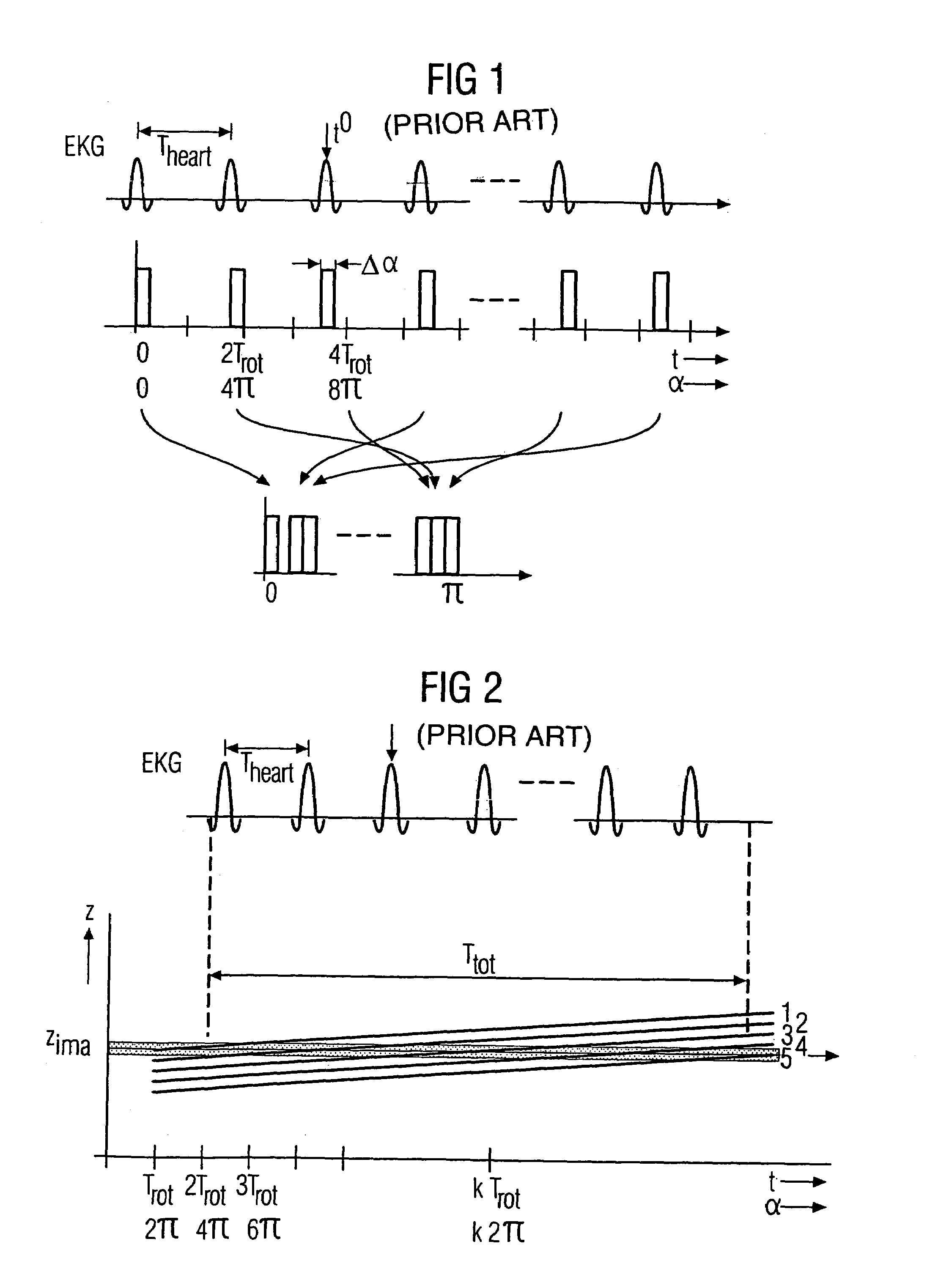
At low heart rates, this leads to such small table advance speeds that, during the customary maximum time for a spiral recording given by the patient's breath holding time, only inadequate object lengths can be covered at the required resolution in the z direction (layer thickness).
Both cases (larger layer thickness and lengthier spiral interpolation) result in a loss of sharpness in the z direction, which is undesirable for imaging fine object structures such as e.g. the coronary arteries.
Although images with good temporal resolution are then obtained, they have inadequate spatial resolution.

Method used


Image

  • Method for examining a body region of an examination object, which body region performs a periodic movement, and CT apparatus for carrying out such a method
  • Method for examining a body region of an examination object, which body region performs a periodic movement, and CT apparatus for carrying out such a method
  • Method for examining a body region of an examination object, which body region performs a periodic movement, and CT apparatus for carrying out such a method

Examples


Embodiment Construction

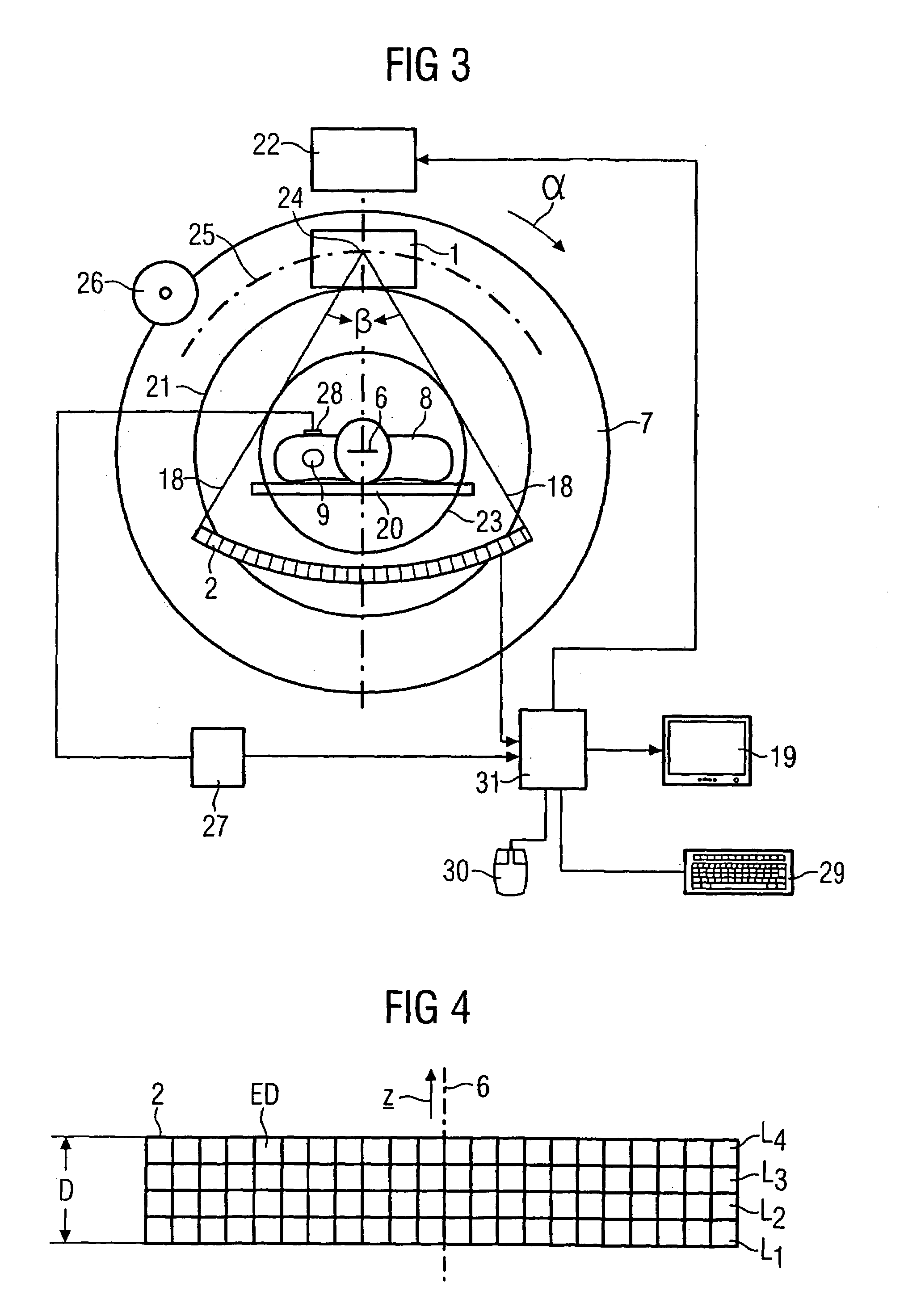
[0027]FIGS. 3 and 4 diagrammatically illustrate a diagnostic apparatus, namely a CT apparatus, for carrying out the method according to an embodiment of the invention.

[0028]The CT apparatus has a measuring unit including an X-ray source 1, which emits an X-ray beam 18, and a detector unit 2, which is composed of a plurality of rows of individual detectors ED, e.g. 512 individual detectors in each case, succeeding one another in the direction of a rotation axis 6, also referred to as system axis. The focus of the X-ray source 1, from which the X-ray beam 18 emerges, is designated by 24. The examination object, a human patient 8 in the case of the exemplary embodiment illustrated, lies on a supporting table 20, which extends through the measurement opening 21 of an annular carrier 7, the so-called gantry.

[0029]In accordance with FIG. 4, the detector unit 2 has a first detector row L1 and a last detector row L4. One or else, as illustrated, a plurality of further detector rows L2 to L3...


PUM


Abstract

A method is for examining a body region of an examination object, which body region performs a periodic movement in the form of a sequence of movement cycles including phases of the periodic movement. The method preferably uses a CT apparatus with a radiation source for generating a radiation that penetrates through the examination object at different projection angles, and a detector system for the radiation emerging from the radiation source. An image, at least of the body region that performs the periodic movement, is determined by way of an electronic computing device from the output data of the detector system, which correspond to the detected radiation and are used as measurement data. In this case, it is provided that, from a number n≧1 of preferably successive movement cycles, data intervals are taken with respect to the same phase of the periodic movement. The overall length of these intervals produces at least one reconstruction interval that suffices for determining an image. The number of movement cycles from which the data intervals of a reconstruction interval originate increases as the frequency of the periodic movement increases, and the length of the data intervals falls as the frequency of the periodic movement increases.

Description

[0001]The present application hereby claims priority under 35 U.S.C. §119 on German patent application number DE 103 33 074.7 filed Jul. 21, 2003, the entire contents of which are hereby incorporated herein by reference.FIELD OF THE INVENTION[0002]The invention generally relates to a method for examining a body region of an examination object. The body region preferably is one which performs a periodic movement in the form of a sequence of movement cycles including phases of the periodic movement. Further, this method may be performed by use of a CT apparatus with a radiation source for generating a radiation that penetrates through the examination object at different projection angles, and a detector system for the radiation emerging from the radiation source. An image at least of the body region, e.g. of a heart, that performs the periodic movement may be determined by way of an electronic computing device from the output data of the detector system, which correspond to the detect...

Claims


Application Information

Patent Timeline
Patent Type & Authority Patents(United States)
IPC IPC(8): A61B6/00A61B6/03
CPCA61B6/032A61B6/4085A61B6/027A61B6/504A61B6/503
Inventor FLOHR, THOMASOHNESORGE, BERND
Owner SIEMENS HEALTHCARE GMBH
Learn More