Method for wavelength switch network restoration

a wavelength switch and network restoration technology, applied in the field of fiberoptic networks, can solve the problems of removing the available network capacity, unable to efficiently utilize the bandwidth of the network, and unable to achieve efficient network utilization, and achieve the effect of restoring connection

Inactive Publication Date: 2006-04-25
LEVEL 3 COMM LLC
View PDF13 Cites 43 Cited by
  • Summary
  • Abstract
  • Description
  • Claims
  • Application Information

AI Technical Summary

Problems solved by technology

However, this approach does not utilize the bandwidth of the network efficiently, i.e., some of the available network capacity is removed for the backup reserve.

Method used


Image

  • Method for wavelength switch network restoration
  • Method for wavelength switch network restoration
  • Method for wavelength switch network restoration

Examples


Embodiment Construction

[0011]Traditional network restoration techniques utilize a central network controller. When the network controller is notified of a network failure, it may signal provisioning information to one or more nodes in the network to implement alternate routes for circuits affected by the failure. The calculation of the alternate routes may occur before or after the failure.

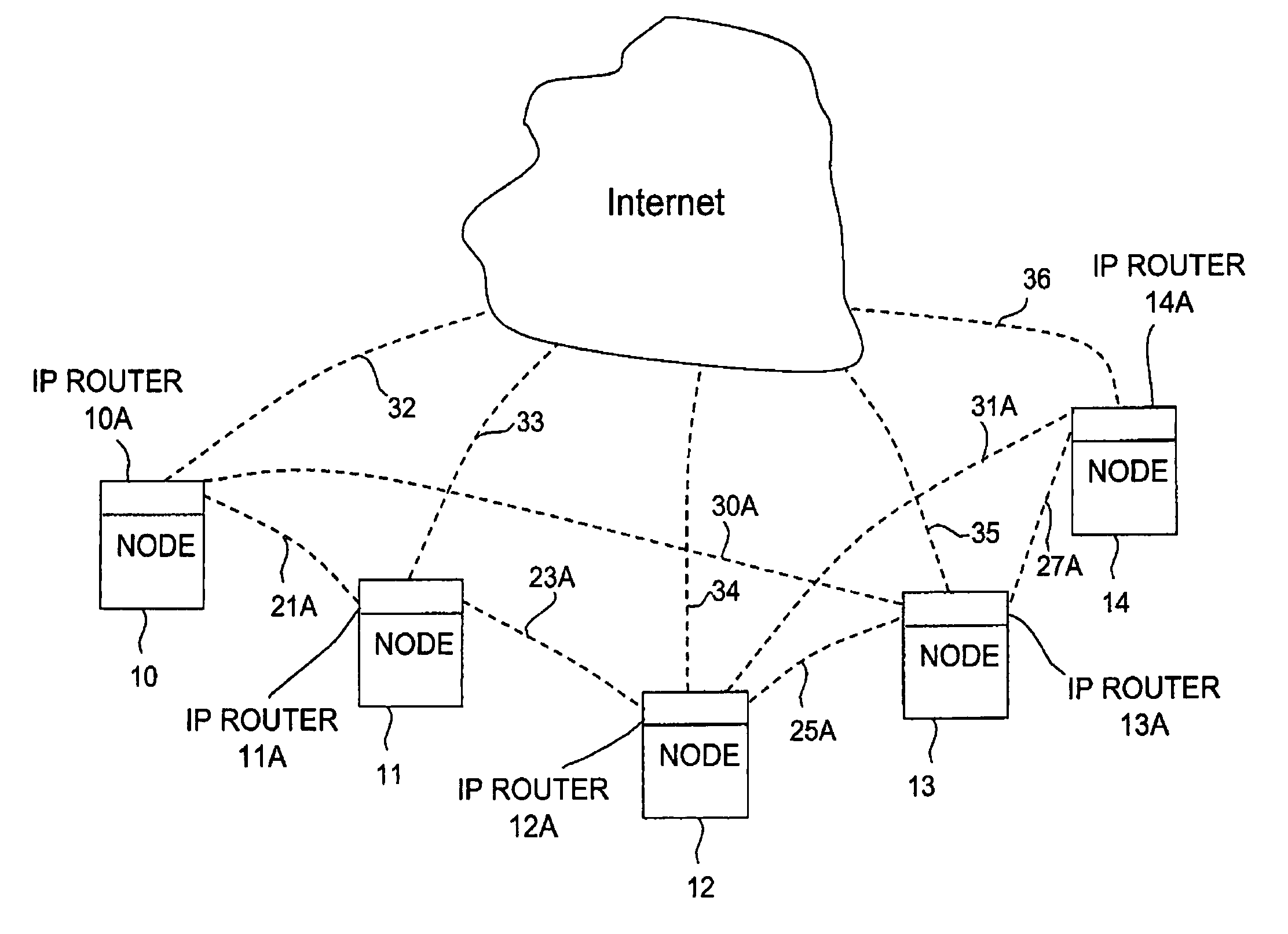
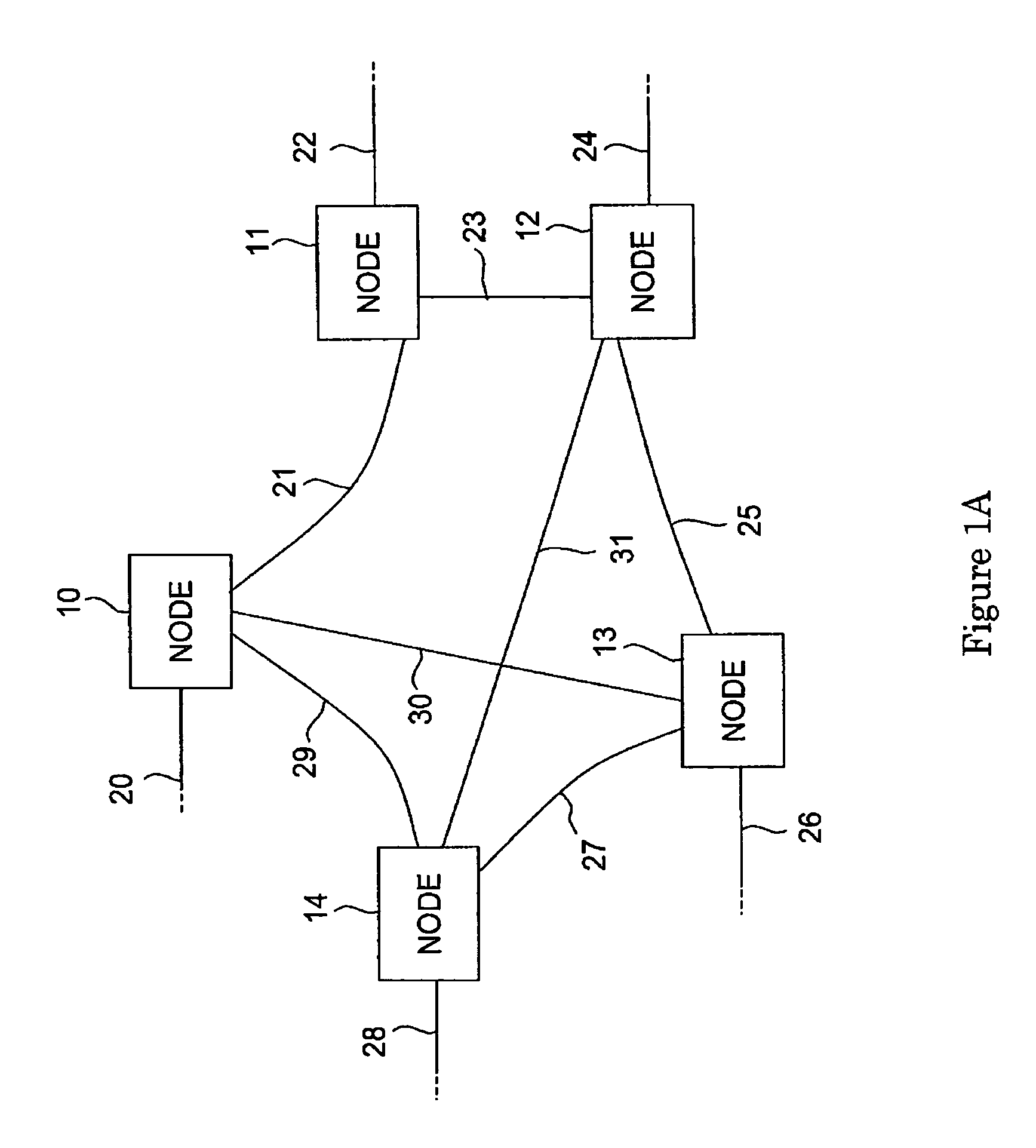
[0012]The present invention seeks to speed up this process by utilizing embedded, distributed control logic in each node. The chief benefit of this distributed approach is a significant saving of signaling times between the nodes of the network. FIG. 1A illustrates an exemplary fiberoptic network with a plurality of switch nodes. Five switch nodes 10–14 have been selected for the purposes of explanation. More or less switch nodes could be used. Each of the switch nodes 10–14 is connected to external data fiberoptic lines 20, 22, 24, 26 and 28 respectively, which are represented by dotted lines. For example, the switch n...


PUM


Abstract

A fiberoptic network with an optical supervisory channel in each of the optical fibers interconnecting the nodes of the network is described. Together with IP routers, the optical supervisory channels form a control network over which signaling and control signals are exchanged by which provisioning and restoration operations are performed at each node. To restore connections between the nodes upon a failure of the network, the control network helps to maintain at each node a synchronized database of network connections between the nodes, send messages to other nodes to initiate restoration operations by a node noticing the failure; and recalculate network connections around the failure by each node from a synchronized database at the node.

Description

CROSS-REFERENCES TO RELATED APPLICATIONS[0001]This patent application claims priority from Provisional Patent Application Nos. 60 / 215,182 and 60 / 215,399, both filed Jun. 29, 2000 and are hereby incorporated by reference.BACKGROUND OF THE INVENTION[0002]The present patent application is related to fiberoptic networks, and, in particular, to switches for WDM and DWDM network systems.[0003]In WDM (Wavelength Division Multiplexing) fiberoptic networks, optical signals are sent at predetermined wavelengths over optical fibers. Each predetermined wavelength forms a communication channel in the network and the wavelength (or frequency) of the optical signal is used to control the destination of the signal through the network. An advanced version of WDM networks is the DWDM (Dense Wavelength Division Multiplexing) network in which the number of wavelength channel is increased by reducing the channel wavelength separation to 100 GHz, as set by the ITU (International Telecommunications Union)...

Claims


Application Information

Patent Timeline
Patent Type & Authority Patents(United States)
IPC IPC(8): H04B10/00H04J14/02H04Q11/00
CPCH04J14/0227H04Q11/0005H04Q11/0062H04J14/0241H04J14/0284H04Q2011/0016H04Q2011/0024H04Q2011/0073H04Q2011/0081H04Q2011/0086H04Q2011/0018
Inventor WANG, DANIELWANG, DAVIDABRAMS, PETERTANG, YAN
Owner LEVEL 3 COMM LLC
Why Eureka
Try Eureka