Integrated conveyor bed

a conveyor bed and integrated technology, applied in the field of conveyors, can solve the problems of consuming a significant amount of both labor and time in custom engineering and design requiring extra time for custom-designed parts and system components, and reducing so as to reduce the amount of labor necessary for the installation and commissioning of prior conveying systems, and facilitate the installation and operation of the system. ,

Inactive Publication Date: 2006-04-25
DEMATIC
View PDF35 Cites 69 Cited by
  • Summary
  • Abstract
  • Description
  • Claims
  • Application Information

AI Technical Summary

Benefits of technology

[0011]The various aspects of the present invention provide an improved conveying system that simplifies the installation, operation, and maintenance of the system. The modularity of the physical conveyor beds, as well as the modularity of the control functions, permits easier installation of conveying systems. The use of automatic self-addressing features further reduces the amount of labor necessary to install a conveying system.

Problems solved by technology

The installation and commissioning of prior conveying systems has typically been a labor-intensive process.
In addition to significant amounts of labor, such custom engineering and design requires extra time for the custom-designed parts and system components to be manufactured.
The installation of conveying systems has therefore consumed a significant amount of both labor and time, all of which translate into increased costs for the customer of the conveying system.

Method used


Image

  • Integrated conveyor bed
  • Integrated conveyor bed
  • Integrated conveyor bed

Examples


Embodiment Construction

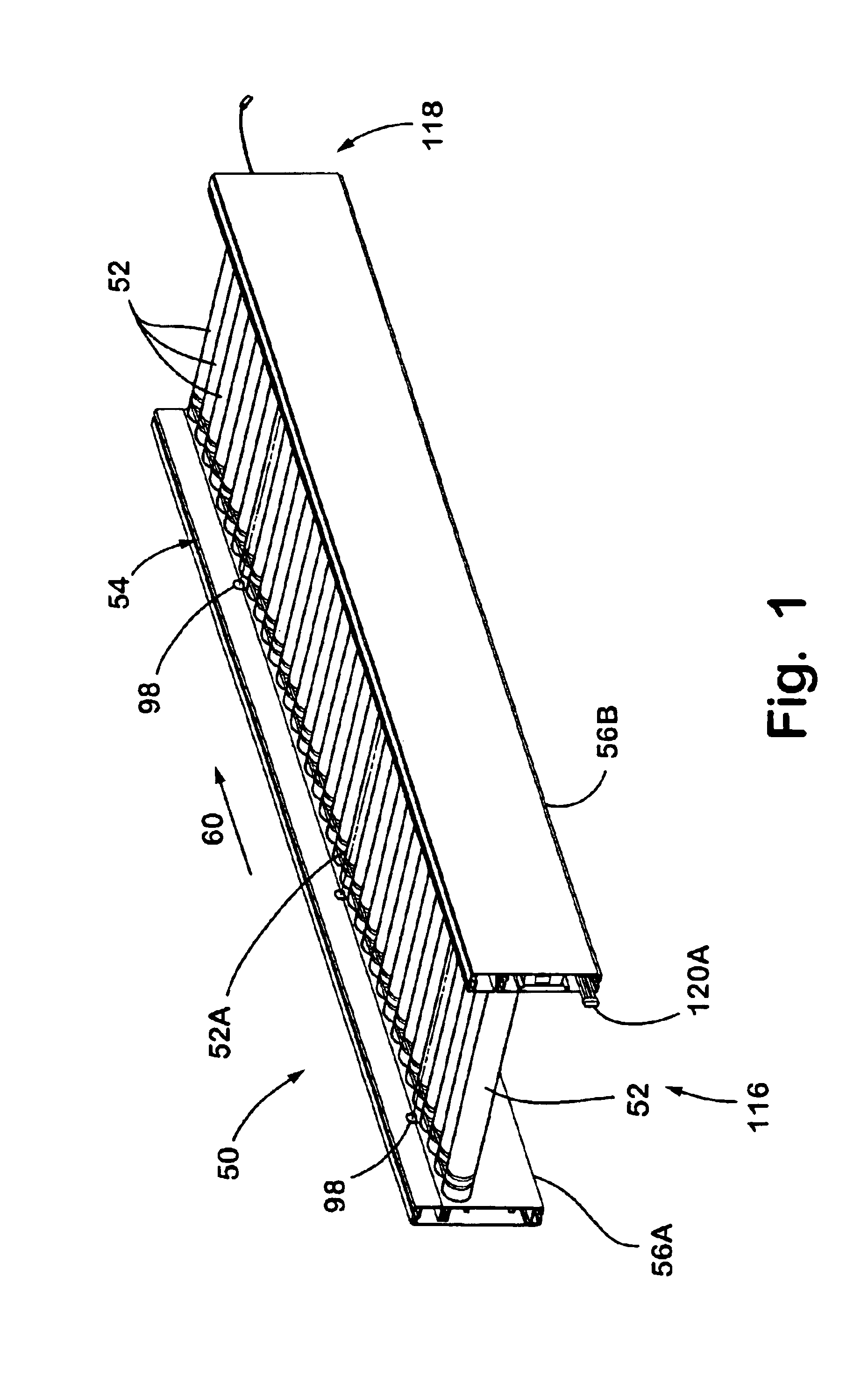
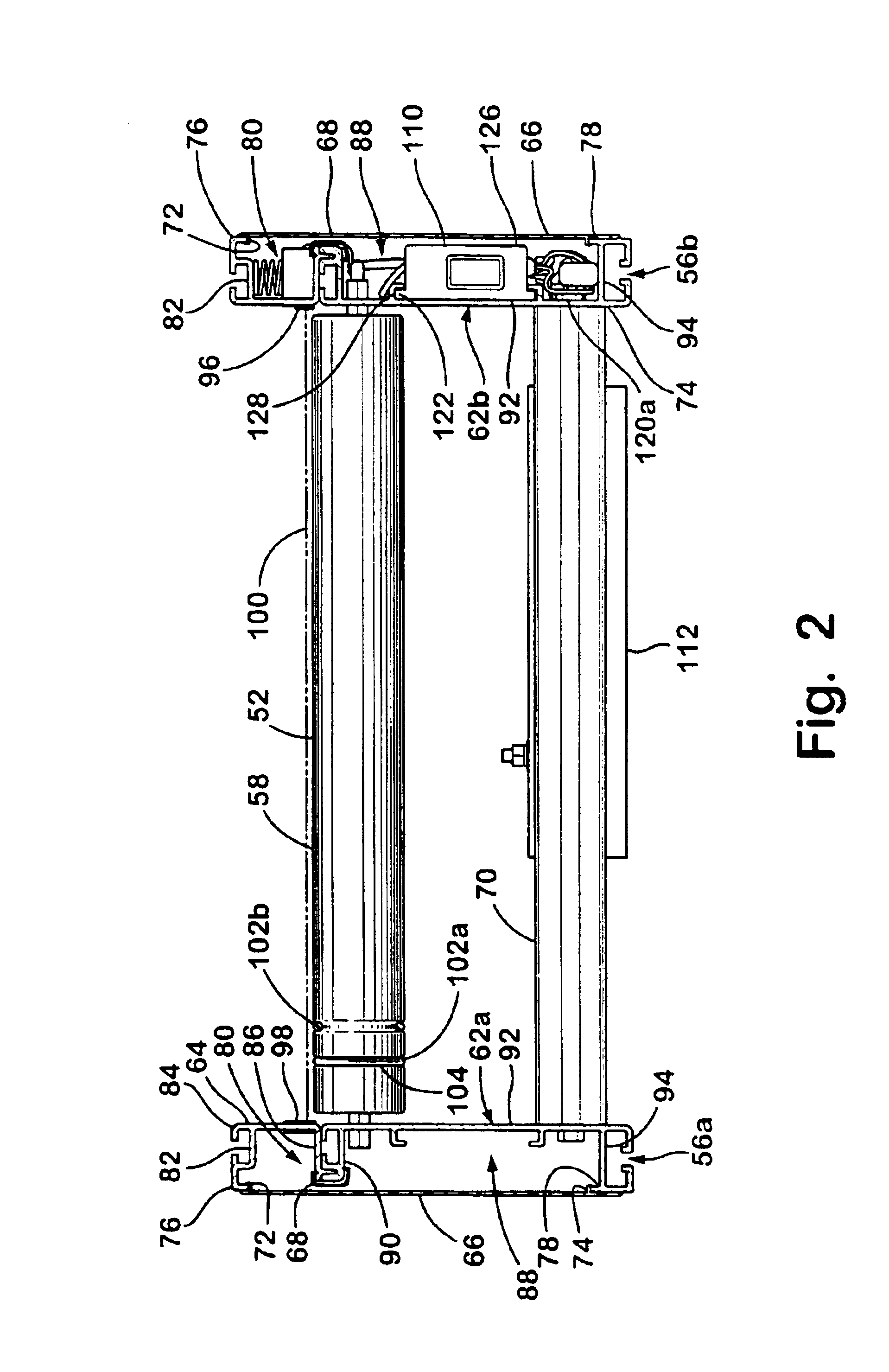
[0052]The present invention will now be described with reference to the accompanying drawings wherein the reference numerals in the following written description correspond to like-numbered elements in the several drawings. A conveyor bed 50 according to one aspect of the present invention is depicted in FIG. 1. Conveyor bed 50 may be a modular unit that may be used as part of a conveying system made up of additional modular conveying units, or a conveying system made up solely of a single conveyor bed. Conveyor bed 50 includes a conveying surface which may be driven by a plurality of rollers 52 that are supported on each of their ends by a frame 54 and driven either through O-rings from a drive, such as a motorized roller, or through an endless member, such as disclosed in commonly assigned application Ser. No. 10 / 411,924, filed Apr. 11, 2003, entitled TAPE DRIVE CONVEYOR which is incorporated herein by reference. Frame 54 includes first and second side members 56a and b. Side memb...


PUM


Abstract

A conveyor system, and method of controlling the conveyor system, includes providing a conveying surface, at least one motor propelling the conveying surface and a plurality of lower-level controllers. At least one of the lower-level controllers adapted to control the at least one motor. An upper-level controller is provided in communication with the plurality of lower-level controllers. The upper-level controller is adapted to send communications to the lower-level controllers for controlling the at least one motor. A communications bus is provided that carries the communications between the upper-level controller and the lower-level controllers. The upper-level controller is adapted to automatically assign each lower-level controller a unique communications address. The unique communications address enables the upper-level controller to send messages over the communications bus to individual ones of the lower-level controllers.

Description

CROSS REFERENCE TO RELATED APPLICATION[0001]This application claims priority from U.S. provisional patent application Ser. No. 60 / 442,311, filed on Jan. 24, 2003, the disclosure of which is hereby incorporated herein by reference in its entirety.BACKGROUND OF THE INVENTION[0002]The present invention relates generally to conveyors, and more particularly to the control, installation, and operation of conveying systems.[0003]Conveyor systems are used in a wide variety of material handling applications. These includes such things as conveying luggage throughout airports conveying parcels through transportation terminals, conveying manufactured parts or components throughout factories, conveying inventory, sorting and conveying items to be transported, and various other applications. Such conveying systems may use conveyors having endless belts that are rotated around end rollers to cause the top surface of the belt to move in the direction of conveyance. Such conveying systems alternati...

Claims


Application Information

Patent Timeline
Patent Type & Authority Patents(United States)
IPC IPC(8): G06F7/00B65G13/02B65G13/06B65G37/02B65G43/00B65G43/08B65G43/10B65G47/26
CPCB65G13/02B65G13/06B65G37/02B65G43/00B65G43/10B65G47/261B65G43/08B65G2203/044B65G2201/025B65G2201/0264B65G39/02
Inventor ANDERSON, KEITH W.PELAK, WYNN M.LUBBERS, LE ROYAFFATICATI, ARTEMIOSCHAUM, FRANK-PETERLAFLEUR, DAVID M.
Owner DEMATIC
Why Eureka
Try Eureka