Architectural trim product

a technology for architectural trim and products, applied in the direction of walls, natural patterns, constructions, etc., can solve the problems of wood having the drawback of periodic maintenance, metal or concrete plastic similar shapes that require complex molds, so as to minimize the tendency of aluminum to bend

Inactive Publication Date: 2006-05-02
ALSCO METALS CORP
View PDF13 Cites 25 Cited by
  • Summary
  • Abstract
  • Description
  • Claims
  • Application Information

AI Technical Summary

Benefits of technology

[0012]The present invention provides an architectural trim product fabricated of sections formed out of aluminum sheet material. The sections have a cross sectional profile shape that includes curved portions and right angle bends. The sections are optionally used as a fascia, a frieze in lengths matching the length of a wall-to-soffit joint, crosshead trim over a window or door or other trim uses. In the crosshead application, the horizontal section piece is mitered at each end and the ends are each closed with a short piece of similar miter-cut section, giving the appearance of a three-dimensional solid. An attaching bolster, or stiffening block, is formed in a shape to fit behind the contour of the trim section to support it to a wall while minimizing the tendency of the aluminum to bend. In all forms, the method of mounting the trim product of the invention to the building structure provides secure attachment with no visible nails, screws, or adhesive.

Problems solved by technology

Forming similar shapes of plastic requires complex molds, and shapes of metal or concrete have traditionally been heavy.
However, wood has the drawback of requiring periodic maintenance in the form of scraping and painting to prevent degradation.
These known plastic trim products require substantial molding investment and capacity to produce, and involve either a substantial inventory or a significant delivery delay to obtain.

Method used


Image

  • Architectural trim product
  • Architectural trim product
  • Architectural trim product

Examples


third embodiment

[0039]Referring now to FIG. 5, the invention is illustrated in side elevation view. A mounting clip 70 is formed with a substantially planar central portion, a bottom lip 72, and a top lip 74. The central planar portion of mounting clip 70 is affixed to wall 62 by any convenient means, e.g. fasteners N, and bottom lip 72 and top lip 74 are not anchored. Bottom lip 72 is formed with its lowermost part spaced from wall 62. Top lip 74 is formed with its uppermost part slightly spaced from wall 62 with an angularly oriented planar portion leading toward its uppermost part.

[0040]Continuing with FIG. 5, face trim 76 is formed to mount onto mounting clip 70. Face trim 76 has bottom hook 78, formed to engage bottom lip 72 of mounting clip 70. Face trim 76 also has top hook 80, formed to engage top lip 74 of mounting clip 70.

[0041]The assembly of face trim 76 to mounting clip 70 is illustrated in sequential steps in FIG. 5A. After bottom hook 78 of face trim 76 has been placed in engagement ...

second embodiment

[0042]Referring now to FIG. 5B, a further profile shape of this second embodiment of the invention is shown. In this profile shape, mounting clip 70 is formed similarly to that discussed and shown above, but face trim 76′ has a more exaggerated profile. Top hook 80′ and bottom hook 78′ securely hold face trim 76′ to mounting clip 70. In this manner, differing architectural styles can be accommodated using the mounting principles described above.

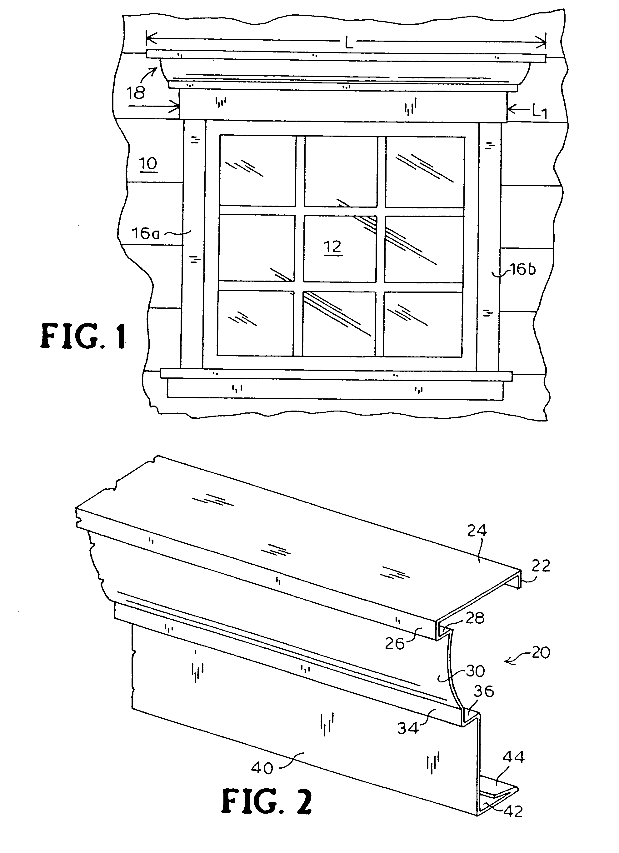
[0043]The face trim products shown in FIGS. 5, 5A, and 5B and described above are adaptable for a variety of interior and exterior construction components. In addition to the exterior components of crosshead, fascia, and frieze described in relation to the first embodiments of the present invention, this second embodiment is useful as crown molding, window or door casings, baseboards, and mantle pieces.

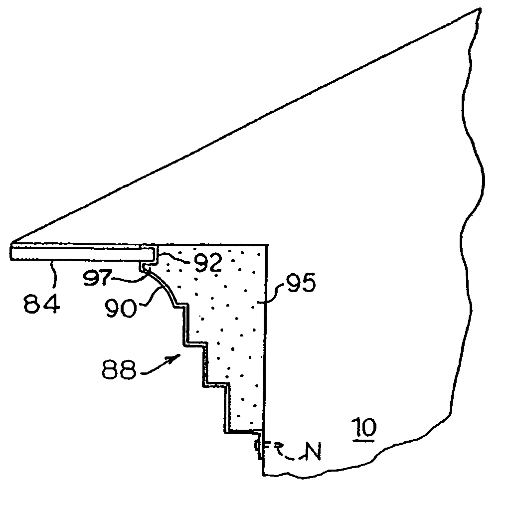
[0044]As briefly described above, a frieze, being a building component that is installed as a transitional trim between a vertical wall and a ...

first embodiment

[0051]Referring now to FIG. 8, a side elevation view is shown of a first embodiment set of forming dies 132, 136 according to the present invention. The solid line drawing shows forming dies 132 and 136 prior to closure with sheet 130 of bendable material in position with surface A painted and surface B unpainted. The dashed line drawing shows formed sheet 130′ after closure of forming dies 132, 136. The lower part of the die set consists of lower die 132, having a selected contour, for example including one or more curved sections and one or more angular sections, and is substantially elongate in a direction perpendicular to the plane of the drawing. Columns 134 support base 132. Upper die 136 is made in a matching contour to the contour of base 132. Form 136 is supported above base 132 by ram 138. Rear lip 22, bottom return 42, and grip 44 (see FIG. 2) are formed in a subsequent bending operation.

[0052]In operation, bendable sheet 130 is placed substantially flat on lower die 132 ...


PUM


Abstract

An elongated horizontal transitional trim product includes an elongated, molded, horizontally-positionable stiffening block. The block has a flat, vertical back surface; a flat, horizontal top surface; a flat, horizontal bottom surface; and a front surface. The front surface extends between an outer edge proximate to the top surface and an outer edge proximate to the bottom surface, and has a cross-sectional profile that includes a plurality of interconnected curved and vertical and horizontal flat surfaces. The stiffening block is capable of being secured directly to a flat, vertical surface of a building. The trim product further includes an elongated deformable metallic sheet terminating in respective upper and lower end sections located above and below a central section. The central section of the metallic sheet includes a plurality of interconnected, continuous surfaces in its cross-sectional profile which mate and snugly fit with the cross-sectional profile of the stiffening block. The metallic sheet is capable of being mounted onto the stiffening block by utilizing the shape of the central, upper, and lower end sections of the sheet to support and maintain the sheet on the stiffening block prior to installing other support means.

Description

[0001]This application is a continuation of application Ser. No. 09 / 714,322, filed Nov. 16, 2000 now U.S. Pat. No. 6,837,020.FIELD OF THE INVENTION[0002]The present invention relates to the field of building construction materials, and more particularly to building architectural trim products.BACKGROUND OF THE INVENTION[0003]The architectural distinctiveness of a house or other building is often attributable to the trim that provides a finishing touch to an otherwise common shape. Trim distinctiveness has, through the years, evolved from Greek, Roman, Gothic, and Victorian to contemporary and modernistic. Each style has various characteristic details and shapes that sets it apart from the others.[0004]Parallel changes have come about through the development of building materials, especially those materials that form the visible surface of a house or building. Common exterior surface materials in use today are wood, brick, vinyl, and aluminum. Vinyl and aluminum have the advantage of...

Claims


Application Information

Patent Timeline
Patent Type & Authority Patents(United States)
IPC IPC(8): E04B2/00E04F13/00E04F19/02E04F19/04
CPCE04F19/02E04F13/00E04F2019/0454E04F2019/0413E04F2019/0431E04F19/0463
Inventor KEDDELL, PETER M.
Owner ALSCO METALS CORP
Why Eureka
Try Eureka