Apparatus for mounting underwater marine detection equipment on a waterborne vessel

Inactive Publication Date: 2006-05-02
HUTCHINSON LEN K
View PDF3 Cites 54 Cited by
  • Summary
  • Abstract
  • Description
  • Claims
  • Application Information

AI Technical Summary

Benefits of technology

[0022]It is understood that the invention is not limited in its application to the details of construction and to the arrangement of the components set forth in the following description or illustrated in the drawings. The invention is capable of other embodiments and of being practiced and carried out in various ways. It is understood that even though the drawings show the members as individual parts, they may be produced as combination member parts. While the member elements are preferably of composite plastics, reinforced plastics or fiberglass, they made be made of metals such as aluminum, for example. Also, it is to be understood that the phraseology and terminology employed herein are for the purpose o

Problems solved by technology

U.S. Pat. No. 4,285,485, incorporated herein by reference, issued on Aug. 25, 1981, is concerned with a transducer mount with limited vertical adjusting capabilities, no means for mounting an underwater viewing camera, no secure means for mounting onto a boat or vessel deck railing, and it is not designed for a deck mounting.
U.S. Pat. No. 4,282,590, incorporated herein by reference, issued on Aug. 4, 1981, is concerned with a transducer mount with limited vertical adjusting capabilities, no means for mounting to a boat deck railing or deck, no means of mounting an underwater viewing camera, no means for protecting the mount from damage upon striking an underwater object

Method used


Image

  • Apparatus for mounting underwater marine detection equipment on a waterborne vessel
  • Apparatus for mounting underwater marine detection equipment on a waterborne vessel
  • Apparatus for mounting underwater marine detection equipment on a waterborne vessel

Examples


Embodiment Construction

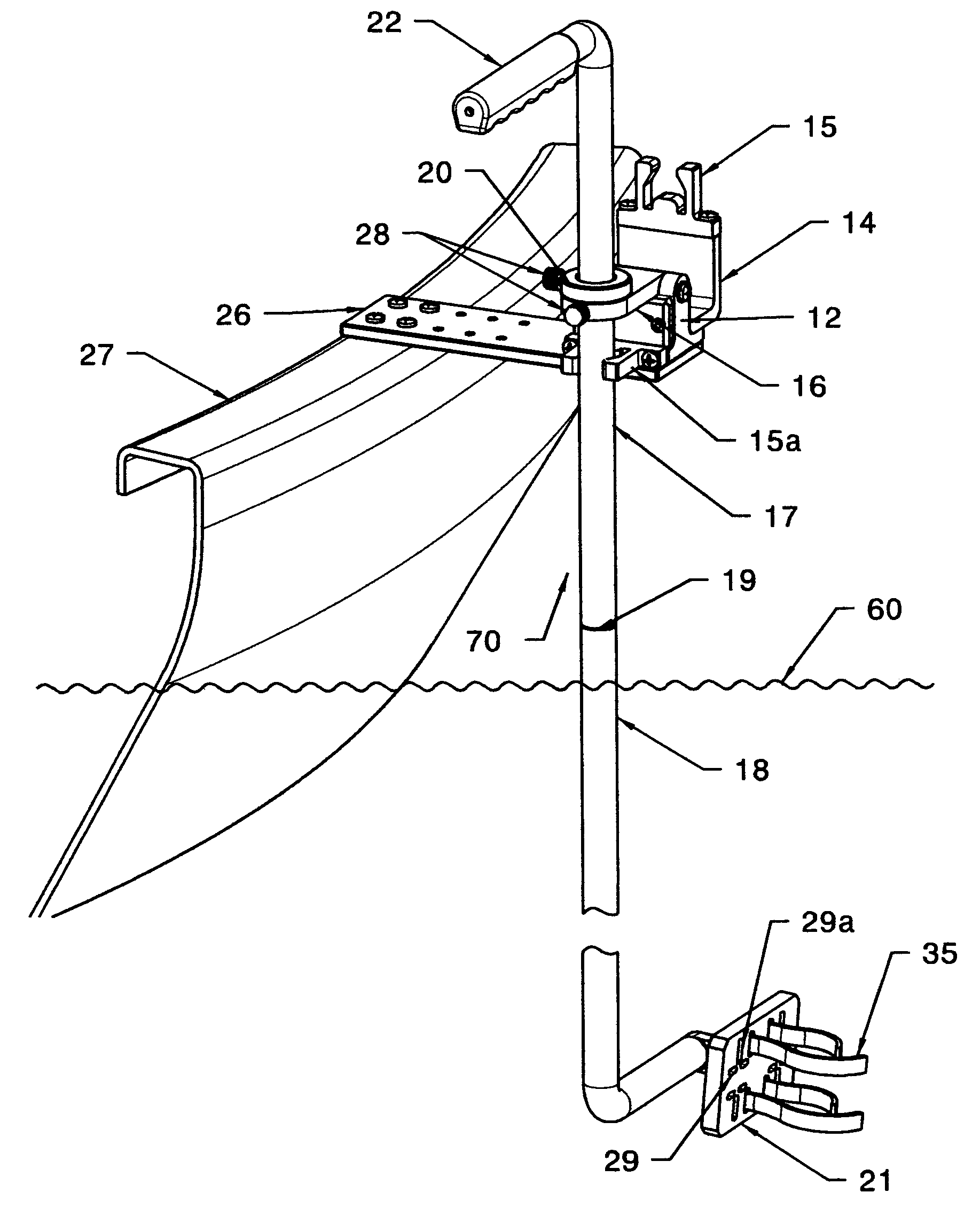
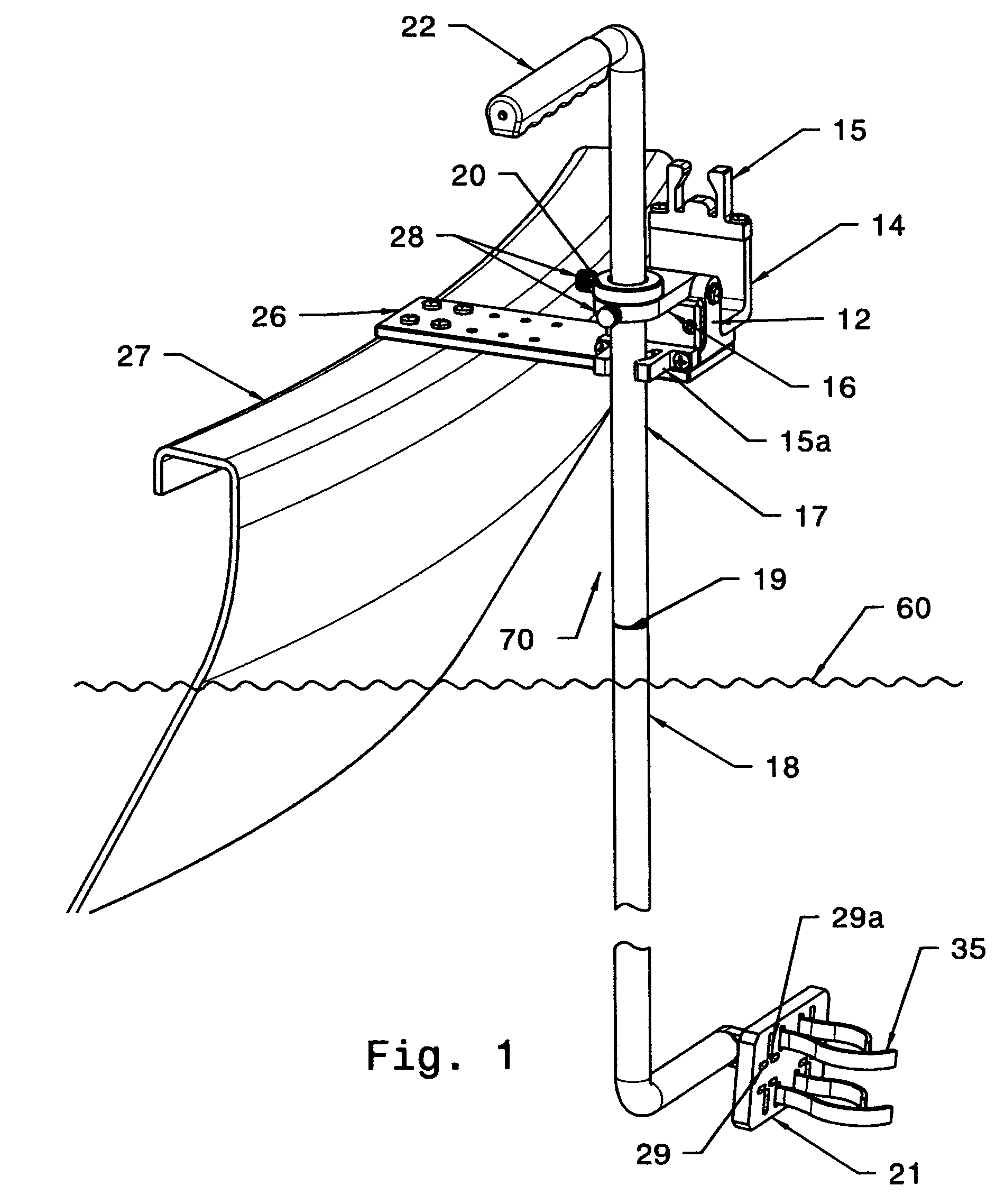
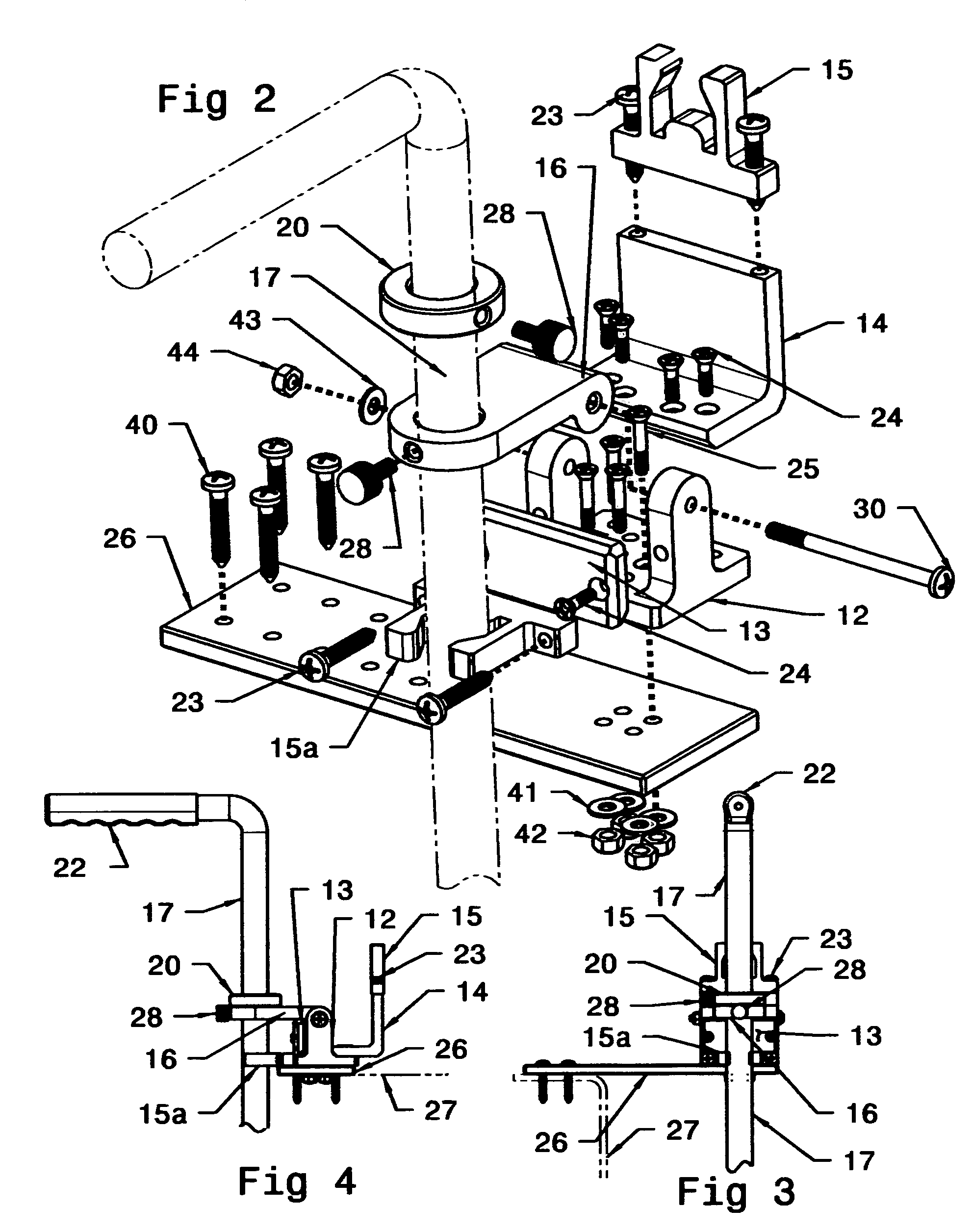
[0036]The present invention is set apart from prior art by providing improved and unlimited horizontal and vertical scanning capabilities, lightweight and corrosion resistant components, a broader selection of mounting capabilities, and the means to attach other underwater scanning devices such as viewing cameras in addition to marine transducers. The present invention will be described in conjunction with accompanying Figures. It is to be understood that the detailed description shows the preferred embodiments, but one skilled in the art may understand that other means and materials may be used to practice the invention as disclosed and claimed. More details of the preferred embodiments, without limiting the scope of the present invention are given herein below.

[0037]Referring now to FIG. 1, according to the present invention an apparatus for mounting underwater marine detection equipment on a waterborne vessel27 is provided in a preferred embodiment as having: a baseplate 26 which...


PUM


Abstract

An apparatus for mounting underwater marine detection equipment on a waterborne vessel is provided having a baseplate which is secured to a side of the waterborne vessel. The baseplate extends outward from the side of the waterborne vessel over the surface of the water. A shaft holder bracket is rotatably mounted to the baseplate such that the shaft holder bracket may rotate in a plane generallyparallel to the forward and reverse direction of the waterborne vessel from a first position to a second position. The shaft holder bracket has a through passageway to receive a shaft. An elongate shaft having an upper portion and a lower portion which are rotatably joined and separable, is slidably engaged through the passageway in the shaft holder bracket, such that the elongate shaft can rotate and slide within the shaft holder bracket. The shaft holder bracket has means to secure the elongate shaft from rotation and sliding. The elongate shaft has a handle on the top of the shaft and a marine detection equipment mount on the bottom of the shaft. The elongate shaft is long enough to extend below the bottom surface of the waterborne vessel when the shaft holder bracket is in the first position, and the elongate shaft is totally out of the water when the shaft holder bracket is rotated to the second position. The marine detection equipment mount is rotatably and adjustably attached to the lower portion of the elongate shaft, such that the marine detection equipment mount can rotate 360 degrees in a plane perpendicular to the surface of the water. The marine detection equipment mount has means to secure marine detection equipment.

Description

CROSS-REFERENCE TO RELATED APPLICATIONS[0001]Not ApplicableSTATEMENT REGARDING FEDERALLY SPONSORED RESEARCH OR DEVELOPMENT[0002]Not ApplicableREFERENCE TO SEQUENCE LISTING, A TABLE, OR A COMPUTER LISTING COMPACT DISK APPENDIX[0003]Not ApplicableBACKGROUND OF THE INVENTION[0004]This invention relates to an apparatus for mounting underwater marine detection equipment on a waterborne vessel, and more particularly for boats as a mounting apparatus for a fishfinder sonar transducer for use in determining depth, assist in navigation, locating fish and scanning for underwater structures, and for mounting a portable underwater camera for viewing fish or structures.[0005]Various types of mounting brackets and apparatus are known in the prior art. For example,[0006]U.S. Pat. No. 6,065,420, incorporated herein by reference, issued on May 23, 2000 is concerned with a portable transducer mount with no means provided for mounting to a boat or vessel deck railing or for mounting to the side walls ...

Claims


Application Information

Patent Timeline
IPC IPC(8): B63B17/00
CPCB63B17/00B63C7/26B63B49/00F16B2/065
Inventor HUTCHINSON, LEN K.
Owner HUTCHINSON LEN K
Why Eureka
Try Eureka