Two-stroke and four-stroke switching mechanism

a switching mechanism and four-stroke technology, applied in mechanical equipment, valve drives, machines/engines, etc., can solve the problems of excessive consumption of fuel, increased power consumption, and increased power consumption of marine engines, so as to maximize power, fuel efficiency, and emissions efficiency

Inactive Publication Date: 2006-05-02
RICARDO INC
View PDF27 Cites 52 Cited by
  • Summary
  • Abstract
  • Description
  • Claims
  • Application Information

AI Technical Summary

Problems solved by technology

The situation for large displacement working vehicles is even more dramatic.
Similarly, marine engines often must shift from high speed or power operation to low speed where the engine operates in idle for long periods of time.
Unused displacement or over displacement results in over-sized, large engines with a multiplicity of cylinders, having a weight and complexity resulting in an unnecessary consumption of fuel and excess pollution.
Existing internal combustion engines are usually limited in their operation to two-stroke or four-stroke cycles.
With fixed compression ratios and limited means of optimizing performance for all ranges of power, torque, and engine speed, fuel consumption is typically characterized by a specific fuel consumption curve with one point of minimum fuel consumption.
Although certain improvements to engine design have addressed these problems, for example, the use of a turbocharger for high performance operation, satisfaction of power demand is at the expense of optimized fuel consumption.
It is, however, inadequate in valve trains where multiple cam profiles actuate the valves through the use of rocker arms or cam followers that by some means switch from one profile to another.

Method used


Image

  • Two-stroke and four-stroke switching mechanism
  • Two-stroke and four-stroke switching mechanism
  • Two-stroke and four-stroke switching mechanism

Examples


second embodiment

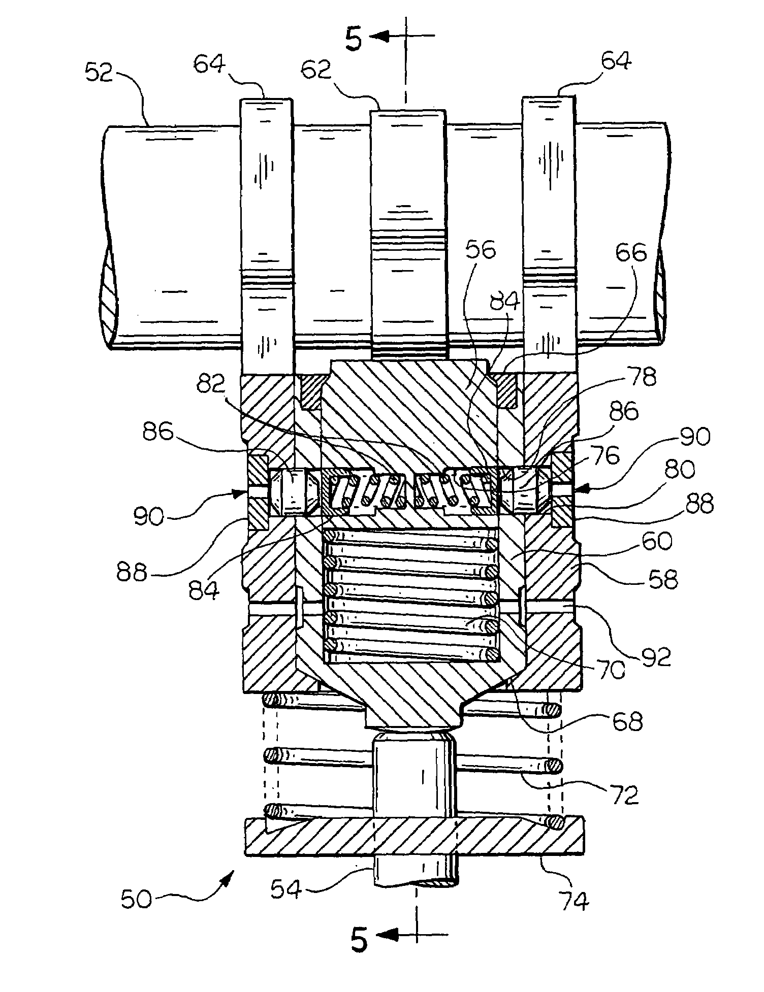
[0033]Referring now to FIGS. 4 and 5, there is shown generally at 50 a schematic front elevational view of a mechanism for switching an engine from one stroke type to another stroke type or switching tappet assembly which represents the present invention. The tappet assembly 50 is disposed between a cam shaft 52 and a valve stem 54. The tappet assembly 50 includes an inner tappet 56 and an outer tappet 58. A valve plunger 60 is disposed between the inner tappet 56 and the outer tappet 58, and is substantially concentric therewith. The inner tappet 56 abuts a four-stroke cam surface 62 of the cam shaft 52 and the outer tappet 58 abuts a pair of two-stroke cam surfaces 64. It is understood that the inner tappet 56 could abut a two-stroke cam surface and the outer tappet 58 could abut four-stroke cam surfaces without departing from the scope and spirit of the invention. An inner tappet stop ring 66 militates against separation of the inner tappet 56 from the valve plunger 60. An outer ...

third embodiment

[0041]the invention is illustrated in FIGS. 12 and 13. In FIG. 12, there is shown generally at 110 a schematic side sectional view of a mechanism for switching an engine from one stroke type to another stroke type or a cam follower and rocker arm assembly. A valve stem 112 abuts an end of a rocker arm assembly 114. A piston 116 is disposed in a hydraulic lash adjustment cavity 118 formed within the rocker arm assembly 114. The piston 116 is urged into engagement with the valve stem 112 by a spring 120. Fluid communication between the hydraulic lash adjustment cavity 118 and a shuttle pin cavity 122 is provided by a first conduit 124. An exhaust orifice 126 provides fluid communication between the shuttle pin cavity 122 and the atmosphere. A second conduit 128 provides fluid communication between the hydraulic lash adjustment cavity 118 and a first axially extending oil supply conduit 130, which is in communication with a first oil supply (not shown). As illustrated, the first oil su...


PUM


Abstract

A switching mechanism capable of switching between a two-stroke and a four-stroke operation of an engine as desired, wherein the switching mechanism is switchable between engagement with a first cam lobe for four-stroke operation and a second cam lobe for two-stroke operation, the four-stroke operation maximizing fuel and emissions efficiency and the two-stroke operation maximizing power.

Description

FIELD OF THE INVENTION[0001]The present invention relates to a switching mechanism and more particularly to a switching mechanism capable of switching between a two-stroke and a four-stroke operation of an engine as desired, wherein the switching mechanism is switchable between engagement with a first cam lobe for four-stroke operation and a second cam lobe for two-stroke operation.BACKGROUND OF THE INVENTION[0002]Conventional internal combustion engines operate according to thermodynamic principles following either a two-stroke cycle or a four-stroke cycle which are commonly classified as a two-stroke engine or a four-stroke engine, respectively. Both types of engines can operate using a range of fuels including gasoline, diesel, alcohol and gaseous fuels. The fuel is typically introduced into the engine using a range of devices including carburetors and fuel injectors, for example. The fuel-air mixture can be ignited by a range of methods including spark ignition and compression i...

Claims


Application Information

Patent Timeline
Patent Type & Authority Patents(United States)
IPC IPC(8): F02B69/06F01L1/08F01L1/14F01L1/18F01L1/36F01L1/46F01L13/00F02B75/02
CPCF01L1/08F01L1/143F01L1/181F01L1/36F01L13/0036F02B75/02F01L1/46F02B2075/027F01L2105/00F02B2075/025F01L2305/00F02B69/06
Inventor BURK, REINHARDWAKEMAN, RUSSELL J.RYAN, RANDALL R.
Owner RICARDO INC
Why Eureka
Try Eureka