
Automobile instrument panel structure

a technology for instrument panels and automobiles, applied in the direction of roofs, pedestrian/occupant safety arrangements, vehicular safety arrangements, etc., can solve the problems of degrading visibility of meter and further degrading of meter visibility, and achieve the effect of enhancing the visibility of an upper meter and a lower meter

Inactive Publication Date: 2006-05-02
HONDA MOTOR CO LTD
View PDF8 Cites 20 Cited by
  • Summary
  • Abstract
  • Description
  • Claims
  • Application Information

AI Technical Summary

Benefits of technology

[0007]The present invention has been accomplished under the above-mentioned circumstances, and it is an object thereof to enhance the visibility of an upper meter and a lower meter provided on an instrument panel main body.

Problems solved by technology

Since the line of sight of the driver is directed substantially toward the front of the vehicle while the driver drivies it, if a meter is disposed at a position that is laterally displaced from the front of the driver, the amount of movement of the line of sight of the driver between when looking at the view in front and when looking at the meter increases, leading to a problem that the visibility of the meter is degraded.
In particular, if the meter is disposed at a position close to the driver, the time taken for focusing the eyes between when looking at the view in front and when looking at the meter becomes long, leading to a possibility that the visibility of the meter might be further degraded.

Method used


Image

  • Automobile instrument panel structure
  • Automobile instrument panel structure
  • Automobile instrument panel structure

Examples


Embodiment Construction

[0052]An embodiment of the present invention is described below by reference to FIG. 1 to FIG. 11.

[0053]The front, rear, left, and right referred to in the present specification are defined so as to correspond to the front, rear, left, and right of a vehicle.

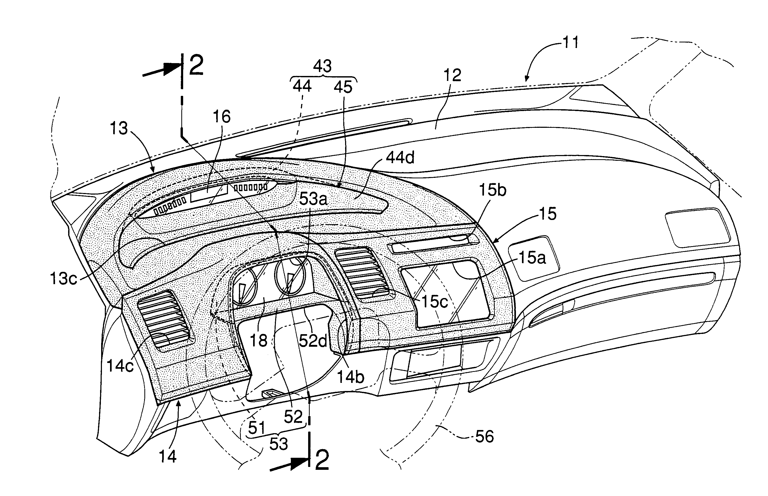
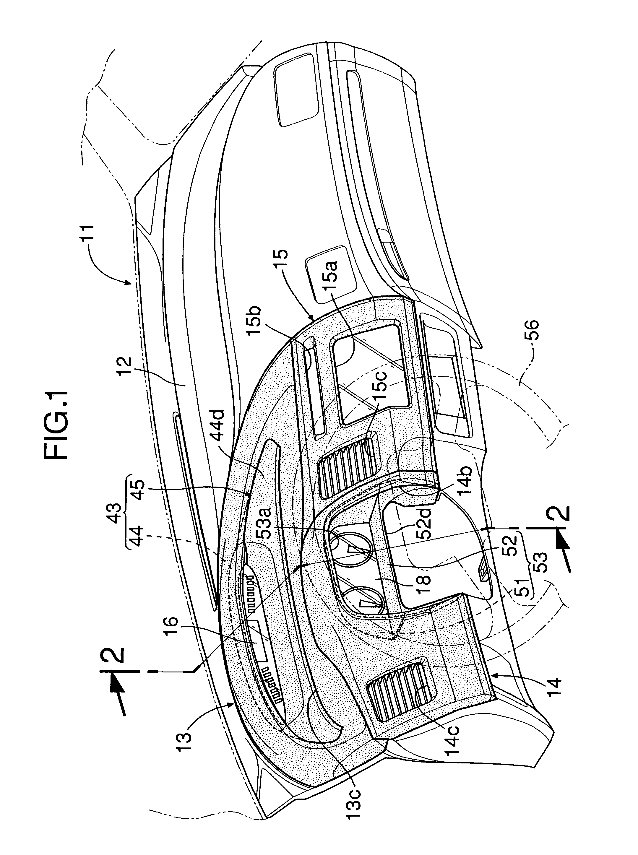
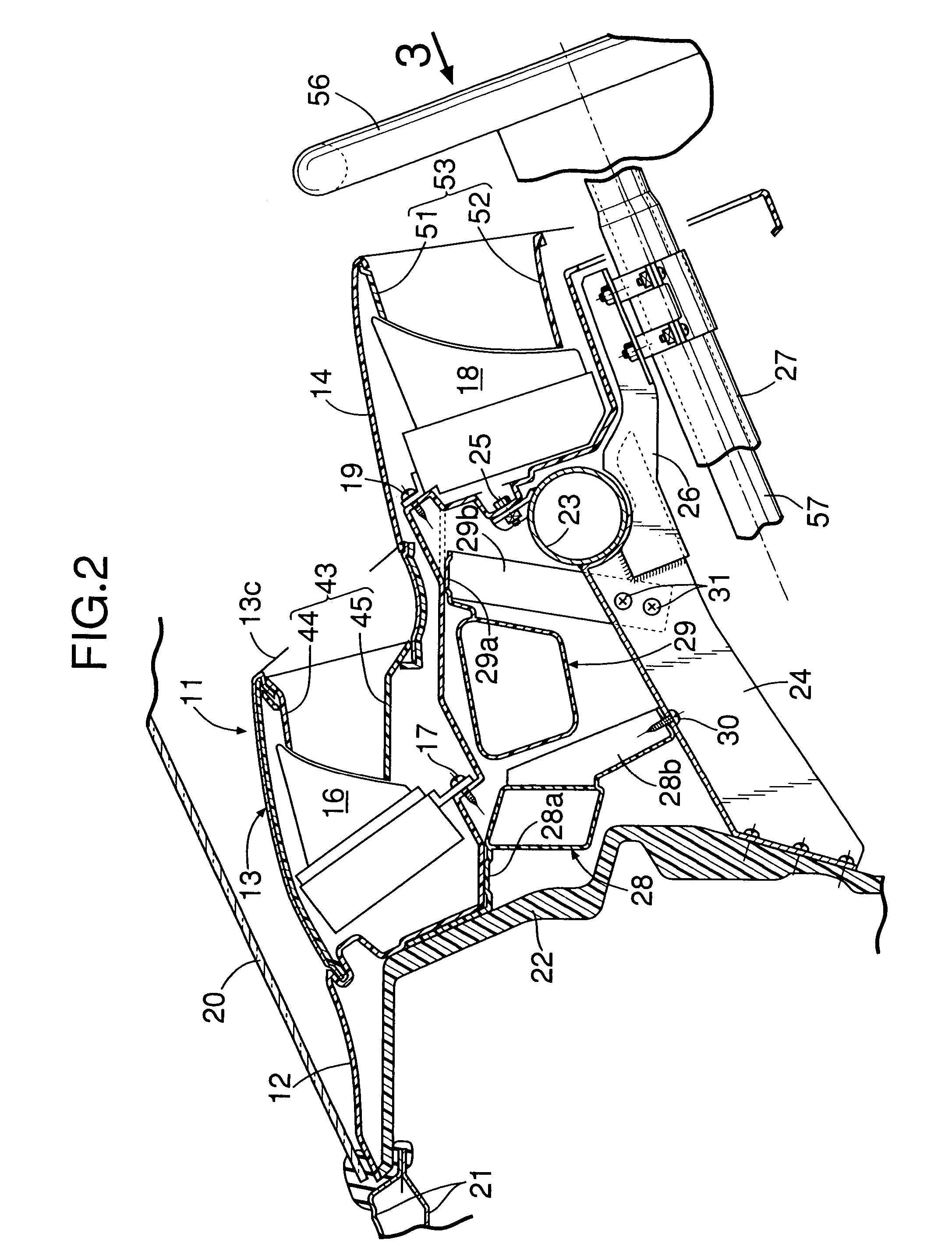
[0054]As shown in FIG. 1 and FIG. 2, an instrument panel 11 that is disposed in a front part of a vehicle compartment of an automobile is formed from an instrument panel main body 12 that is molded as a unit from a synthetic resin, and an upper panel 13, a lower left panel 14, and a lower right panel 15, which are all mounted on a rear face of the instrument panel main body 12 at positions forward of a driver's seat and are all made of a synthetic resin. The instrument panel main body 12 is a sheet-like member that drops stepwise from the front to the rear; an upper meter 16 is fixed to a front portion of the instrument panel main body 12 at a high position by means of a tapping screw 17 so as to face rearward, and a lower meter...


PUM


Abstract

In an automobile instrument panel structure, an upper meter provided in an upper front part of an instrument panel main body is disposed so as to correspond to an upper side of an upper half of a steering wheel, and a lower meter provided in a lower rear part of the instrument panel main body is disposed so as to correspond to a lower side of the upper half of the steering wheel. It is thus possible to reliably view the upper meter and the lower meter without being obstructed by the steering wheel. Further, since an upper edge of a panel in which the upper meter is disposed has a shape substantially conforming to the upper half of the steering wheel, there is no disagreeable sensation even when the upper meter, which has conventionally been disposed in a laterally central part of the instrument panel main body, is disposed in front of the driver. Furthermore, since the panel can be attached to and detached from the instrument panel main body, maintenance can easily be carried out for the upper meter and the lower meter by removing the panel.

Description

RELATED APPLICATION DATA[0001]The Japanese priority application Nos. 2004-114105, 2004-114106, 2004-114107 and 2004-114108 upon which the present application is based are hereby incorporated in their entirety herein by reference.BACKGROUND OF THE INVENTION[0002]1. Field of the Invention[0003]The present invention relates to an automobile instrument panel structure in which an upper meter and a lower meter are respectively supported on an upper front part and a lower rear part of an instrument panel main body, and a panel is detachably fixed to the instrument panel main body so as to surround the perimeter of the upper meter and the perimeter of the lower meter.[0004]2. Description of the Related Art[0005]Japanese Patent Application Laid-open No. 2000-168400 discloses an arrangement in which an entertainment display for displaying information such as road map information that contains a large amount of information but has low urgency, is disposed in a central position in the vehicle ...

Claims


Application Information

Patent Timeline
Patent Type & Authority Patents(United States)
IPC IPC(8): B62D25/14B60K37/00B60K37/02
CPCB60K37/02B62D25/14B60K2350/946B60K2350/941B60K2370/81
Inventor SATO, TADASHIFUKUSHIMA, TETSUJIKABAYAMA, HIDETOSHICHINZAI, NAOYA
Owner HONDA MOTOR CO LTD
Learn More