Method and apparatus for an improved lock and dam assembly

a technology of lock and dam and miter gate, which is applied in the direction of barrage/weir, marine site engineering, construction, etc., can solve the problems of linear cracking, high stress on the web plate, and large force required for closing the system, so as to minimize the strain on the web plate

Inactive Publication Date: 2006-05-02
JOHNSON MACHINE WORKS
View PDF5 Cites 13 Cited by
  • Summary
  • Abstract
  • Description
  • Claims
  • Application Information

AI Technical Summary

Benefits of technology

[0016]The present invention generally comprises a method of constructing a miter gate system that uses a girder, stiffener and web plate grid structure to support a plurality of diaphragms. More specifically, the present invention includes securing the vertical thrust plates to the girder, stiffener and web plate grid support structure by forming a slot in the web plates on the quoin and miter ends of the gate. The series of thrust plates are welded to one another to act as one and are inserted into the groove of the end web plates. In the groove or slot, the thrust plates are fillet welded to the web plate to secure the thrust plate assembly in place. Such an assembly process allows the thrust plates to transfer the impact stresses associated with closing directly to the girder, stiffener and web plate grid support structure which transfers the stresses to the thrust plates on the opposite end and out to be dissipated in the ground. By providing a solid thrust plate arrangement, the closing impact stresses need not flow into the end web plate, thus minimizing strain in the web plate.

Problems solved by technology

Closing the system requires a great deal of force.
Because the thrust plates are secured to the web plates in sections and welded in place to the web plates using a T-joint weld, the stress tends to flow into the web plates creating destructive strains.
Because the miter gate will go through many opening and closing operations during its useful life, the resultant cyclical loading strains in the web plates causes linear cracking over time.
The cracking, or laminar tearing, detrimentally affects the useful life of the miter gate system.
Not only would extensive pre-stressing add significantly to the construction costs, but because of the large sizes associated with nearly every miter gate system, such a pre-stressing process would also add significantly to the time needed for construction.

Method used


Image

  • Method and apparatus for an improved lock and dam assembly
  • Method and apparatus for an improved lock and dam assembly
  • Method and apparatus for an improved lock and dam assembly

Examples


Embodiment Construction

[0024]The present invention will now be described according to its preferred embodiment. It should be understood that the present invention is not limited to the embodiment described.

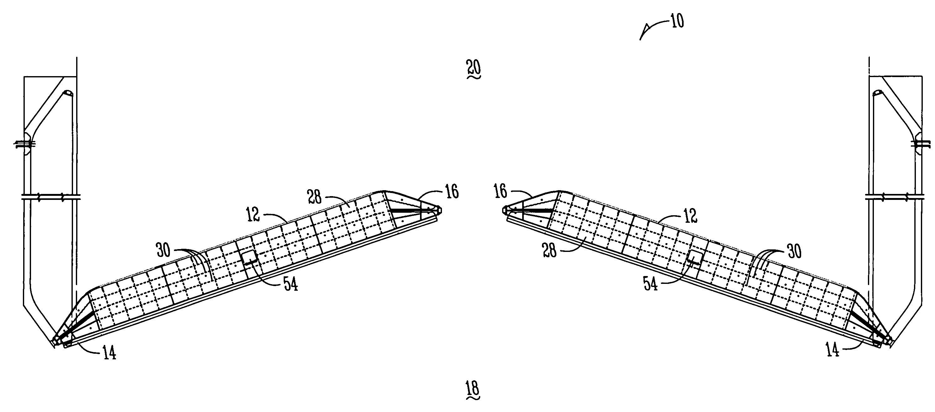
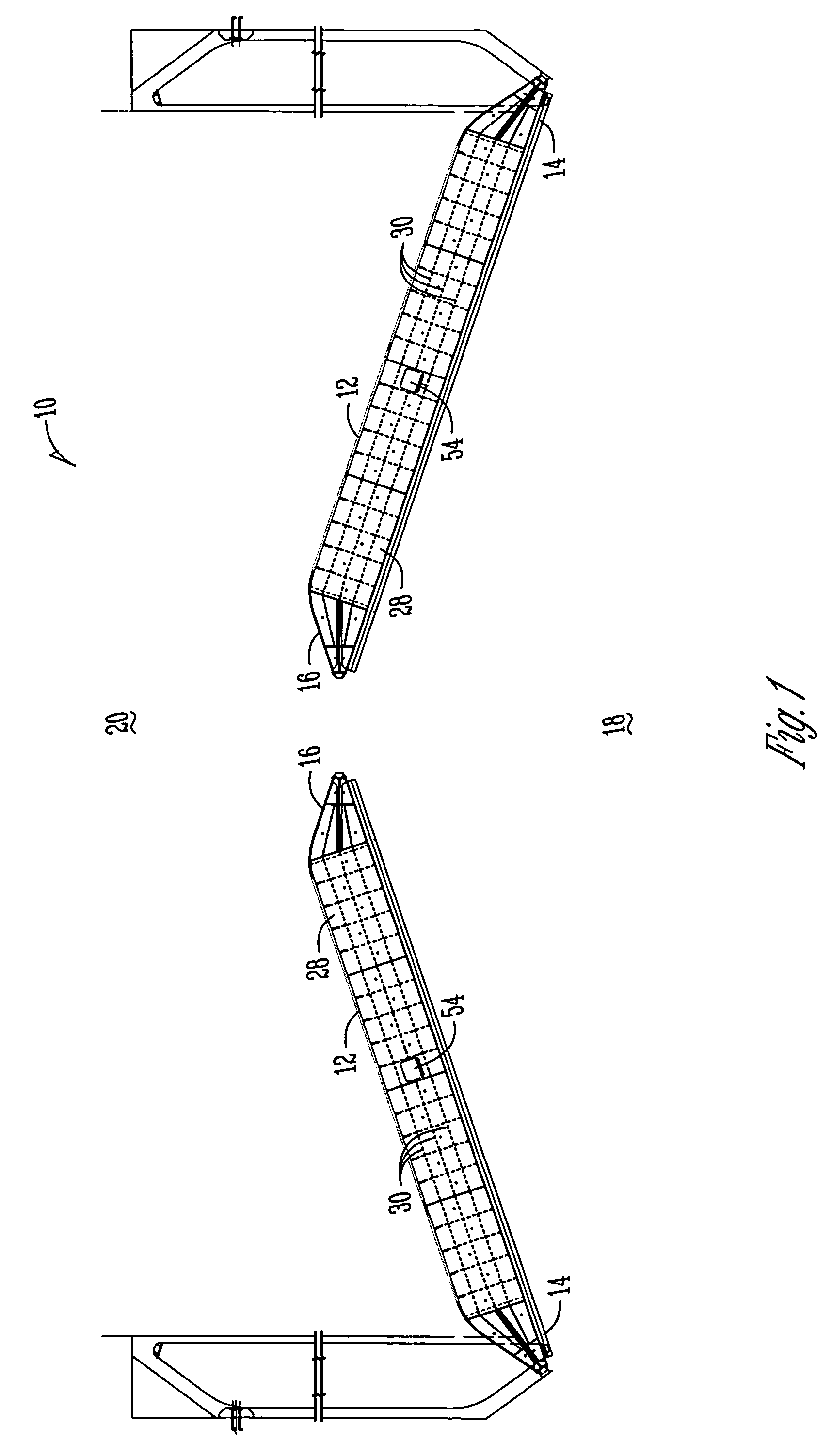
[0025]As is shown in FIG. 1, the preferred lock and dam system 10 includes at least one, and usually a plurality of gates 12. The gates 12 have what are commonly referred to as a quoin end 14 and a miter end 16. In operation, the gates 12 rotate at the quoin end 14 and come together at the miter end 16. When the gates 12 come together, they block flow of water from the upstream location 20 to the down stream location 18 thereby allowing the controlling authority, typically a unit of the Army Corps of Engineers, to control the level of water in the lock and dam system 10.

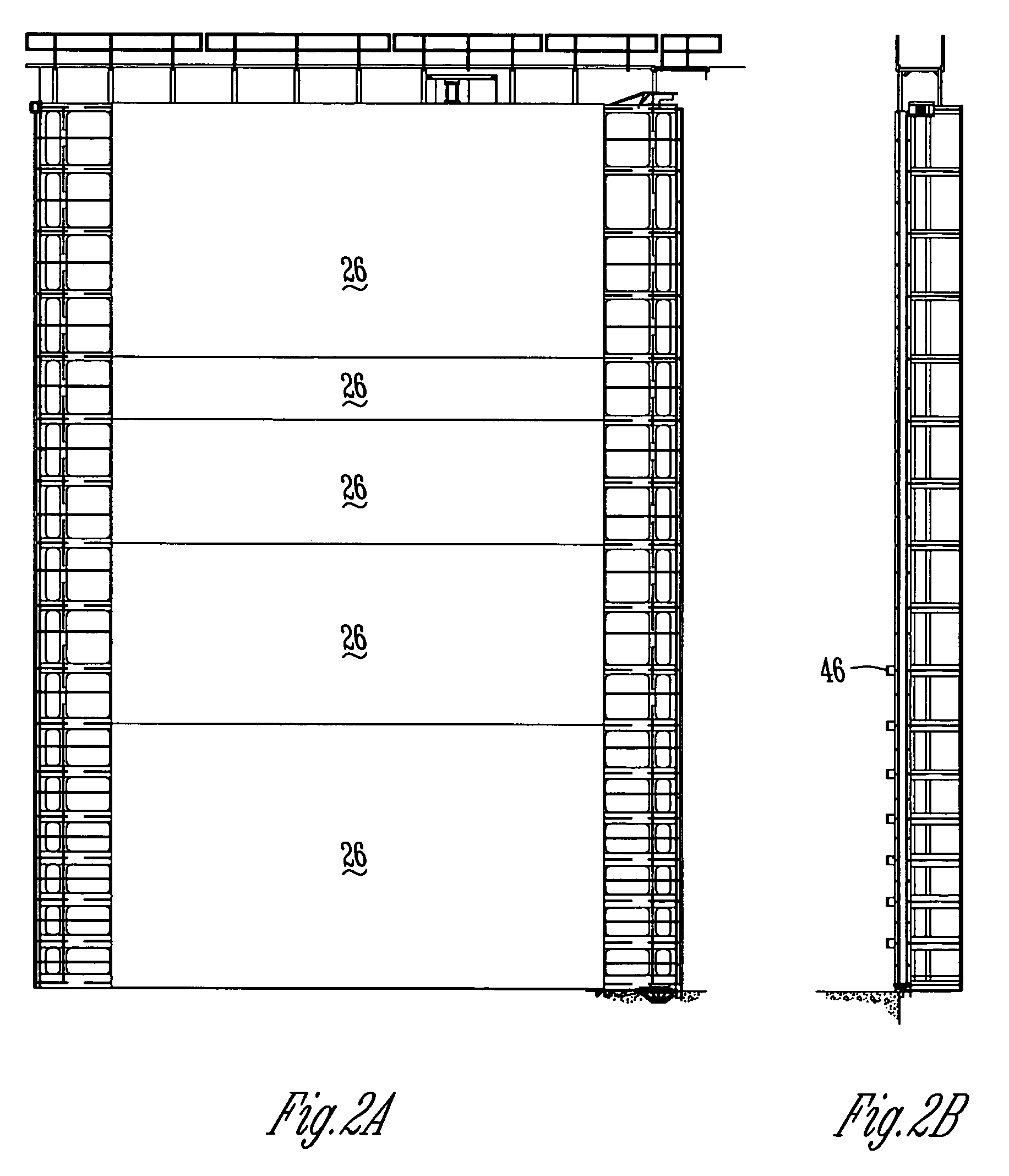
[0026]Each gate 12 in the lock and dam system is typically made of a number of elements. Most of the elements are preferably A709 Gr. 50 steel. For example, a typical gate 12 includes a number of girders 22 assembled through welding and ...


PUM


Abstract

A method of assembling a lock and dam system is disclosed to minimize the rate of structural fatigue associated with closing of the lock and dam system. The lock and dam system includes one or more gates that may include a plurality of girders, plates and associated support or reinforcing members. The gate has a miter end and a quoin end. On the miter end a miter block, and thrust plate transfer impact forces associated with closing of the gate from the point of impact to the remainder of the gate. The thrust plate is preferably a substantially uniformly thick member that is secured vertically to the gate through a slot cut or formed in the end of the horizontal plate on the miter and quoin end. Preferably, the thrust plate is secured using a fillet weld.

Description

BACKGROUND OF THE INVENTION[0001]The present invention relates generally to a method of building miter gates within a lock and dam system and more particularly to a method of construction that reduces the rate of structural fatigue associated with use of the miter gates within the lock and dam system.[0002]1. Status of the Art[0003]Miter gates have been in use throughout the United States for a number of years. Typically made of steel, these gates within the lock and dam systems, provide ways for boat and barge traffic to safely navigate controlled water ways.[0004]A controlled water way, such as the Mississippi river, may have several lock and dam systems along its route. When in a locked position, the system blocks water upstream from flowing downstream and thus allows a controller, such as the Army Corp of Engineers, to raise and lower the water level as required. After proper adjustment, the system can be opened to allow for water traffic to pass.[0005]After all traffic has clea...

Claims


Application Information

Patent Timeline
Patent Type & Authority Patents(United States)
IPC IPC(8): E02B7/40
CPCE02B7/40
Inventor WERTS, R. KELLEY
Owner JOHNSON MACHINE WORKS
Why Eureka
Try Eureka