Refuse collection vehicle having multiple collection assemblies

a technology of refuse collection and assembly, which is applied in the direction of packaging bottles, transportation and packaging, packaging goods types, etc., can solve the problems of difficult operation, mechanical complexity, and limited reach of systems in accessing containers, and achieves reduced dumping height, increased reach, and improved service life.

Inactive Publication Date: 2006-05-02
HEIL CO THE
View PDF16 Cites 20 Cited by
  • Summary
  • Abstract
  • Description
  • Claims
  • Application Information

AI Technical Summary

Benefits of technology

[0007]Another advantage of the invention is that it has a lower dumping height and a lower retracted profile than was previously known for refuse collection and dumping devices.
[0008]Still another advantage of the invention is that it operates in a smoother manner than previously-known devices, which offers increased life of assembly components, improved reliability of operation, and a reduction in the vibrations that are transmitted to the operator compartment. Another advantage of a preferred embodiment of the invention lies in the fact that it employs a pair of primary hydraulic actuators (lift and reach actuators) which are arranged and configured so that the “stroke” of each of the actuators retracts the piston into the actuator body, so that if the seals of an actuator leak hydraulic fluid, the actuator will tend to retract the assembly rather than extend it.
[0009]Yet another advantage of a preferred embodiment of the invention is that it offers an enclosed gearbox for the grab assembly, which offers more protection for the components of the grab assembly and consequently improved operation of such components than previously-known devices.
[0010]Additional objects and advantages of this invention will become apparent from an examination of the drawings and the ensuing description.EXPLANATION OF TECHNICAL TERMS
[0011]As used herein, the term “operating cycle” refers to the cycle during which the apparatus of the invention reaches for a container, grabs a container, lifts a container, dumps the container into a collection bin, returns the container to its point of origin, releases the container and retracts to its retracted or travel position.
[0012]As used herein, the terms “reach” and “extension” refer to that portion of the operating cycle during which the apparatus extends from its retracted or travel position to the location of a refuse container.

Problems solved by technology

Such vehicles may introduce refuse into the collection bin from the front, rear or side of the vehicle.
Some of the known systems offer a limited reach in accessing a container.
Some are unable to grab a container that is not on the same level as the vehicle.
Some are mechanically complex and difficult to operate.
Some protrude from the vehicle on which they are mounted to such an extent that they present a risk of hitting other vehicles, mailboxes or other roadside obstacles.
Some are slow to complete their operating cycle, and some are expensive to build and install.

Method used


Image

  • Refuse collection vehicle having multiple collection assemblies
  • Refuse collection vehicle having multiple collection assemblies
  • Refuse collection vehicle having multiple collection assemblies

Examples


Embodiment Construction

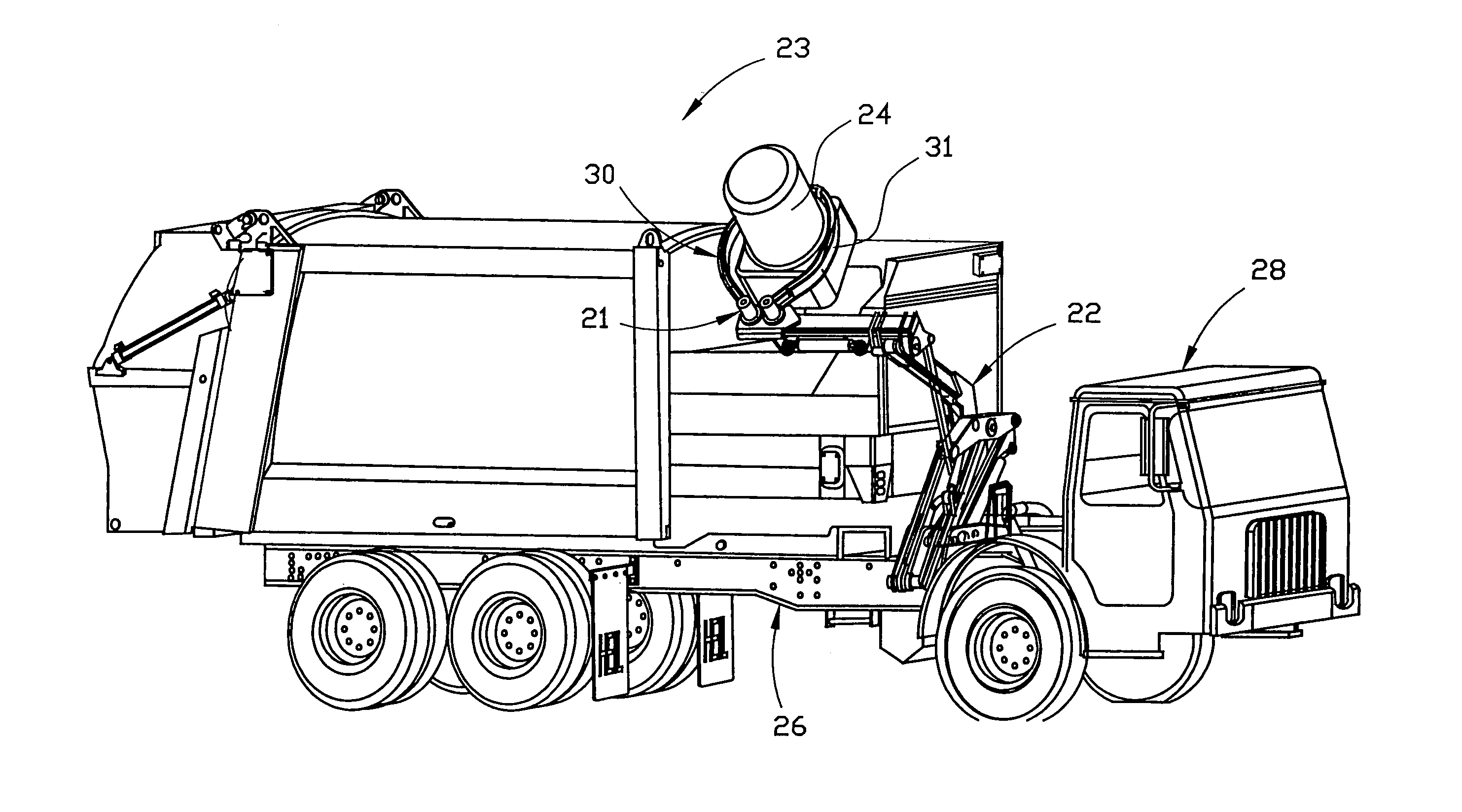
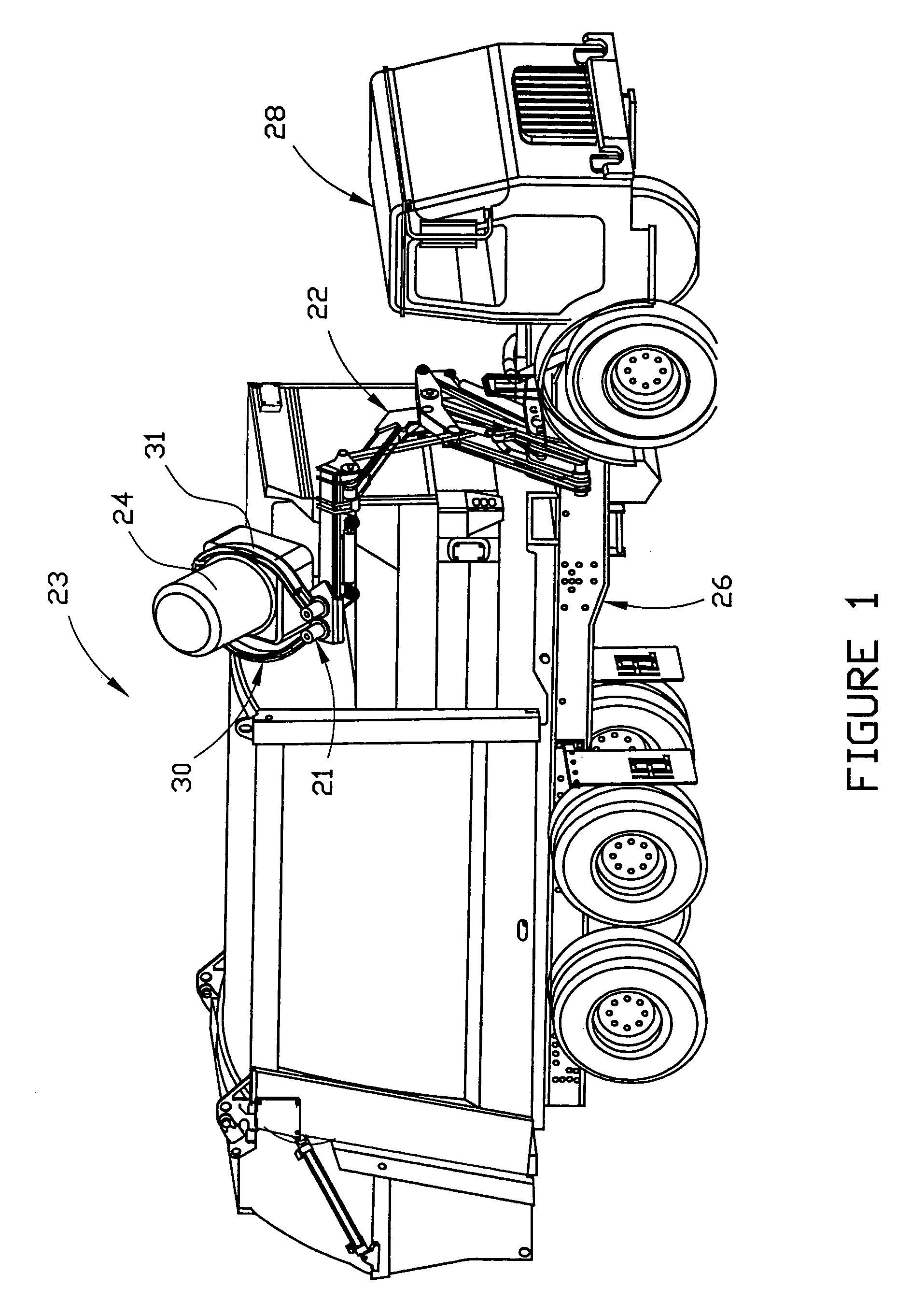
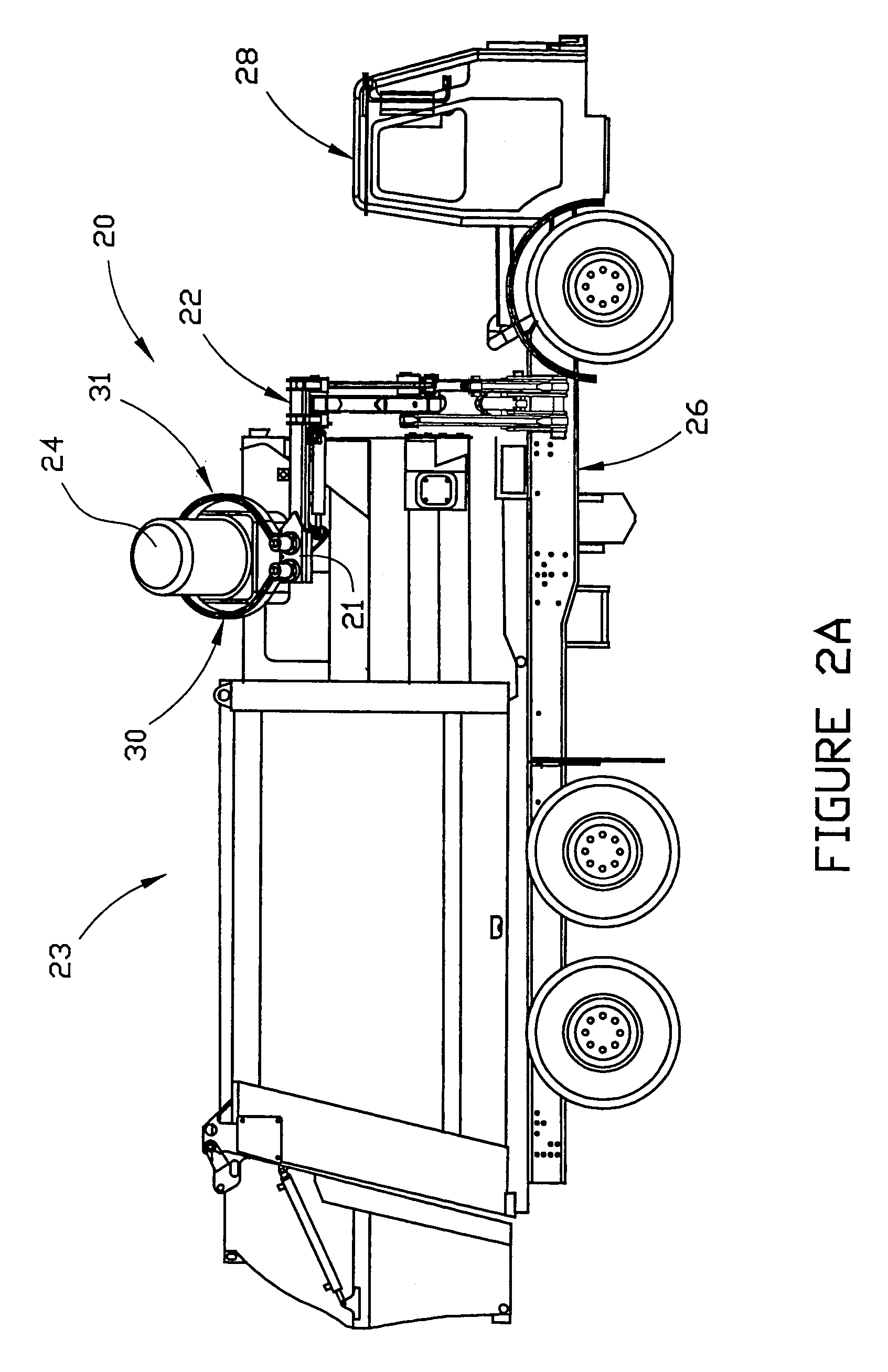
[0051]As shown in the drawings, the invention comprises an apparatus for grabbing or acquiring, lifting and transporting a container so as to deposit its contents in a collection bin. The preferred apparatus 20 includes container grab assembly 21 and articulated, moveable arm assembly 22. As shown in FIGS. 1, 2A, 3 and 4, preferred embodiment 20 of the invention is adapted for use in connection with a refuse collection vehicle such as vehicle 23, which may be used to collect trash and refuse from containers such as container 24 that are placed curbside (or at another convenient location) in a residential area. As shown in FIGS. 1, 2A and 4, arm assembly 22 of preferred grab and lift mechanism 20 is preferably attached (by welding, bolting or other suitable means) to frame 26 of the vehicle behind operator's cab 28. The arm assembly is operable by a fluid-operated actuating system (as described in more detail hereinafter) through an operating cycle that includes a retracted position ...


PUM


Abstract

A refuse collection vehicle includes a collection bin that is mounted on the vehicle frame, and an apparatus for acquiring, lifting and transferring a container so as to deposit the contents of the container in the collection bin. The vehicle also includes a collection compartment that is pivotally mounted on the rear of the vehicle, a storage compartment that is mounted on the frame between the collection bin and the collection compartment, and a packer blade that is mounted within the collection compartment and moveable so as to move refuse material from the collection compartment into the storage compartment.

Description

CROSS REFERENCE TO RELATED APPLICATIONS[0001]This application is a divisional application of U.S. patent application Ser. No. 09 / 975,759, entitled MECHANISM FOR DUMPING A REFUSE CONTAINER, which was filed on Oct. 11, 2001 now U.S. Pat. No. 6,781,523. This application also claims the benefit of U.S. Provisional Application No. 60 / 240,255, which was filed on Oct. 13, 2000, through the aformentioned parent application.FIELD OF THE INVENTION[0002]This invention relates generally to an improved refuse collection device, and more particularly, to an improved refuse collection device which is adapted to grab and lift a refuse container and dump the contents thereof into a collection bin. Preferably, the collection device is mounted on a refuse collection vehicle. Such device may be employed to grab and lift a residential-type refuse container from a curb-side or other convenient location, raise the container to dump it into a collection bin on the vehicle, and return the container to its o...

Claims


Application Information

Patent Timeline
Patent Type & Authority Patents(United States)
IPC IPC(8): B65F3/04B65F3/02B65F3/06B65G3/04
CPCB65F3/048B65F3/06Y10S414/13B65F2003/023
Inventor HUND, JR., HENRY M.KELLER, MARK A.
Owner HEIL CO THE
Why Eureka
Try Eureka