Car control apparatus and control method

Inactive Publication Date: 2006-05-02
HITACHI LTD +1
View PDF8 Cites 7 Cited by
  • Summary
  • Abstract
  • Description
  • Claims
  • Application Information

AI Technical Summary

Benefits of technology

[0010]By use of such a constitution, the load of the synchronizer i

Problems solved by technology

Therefore, when the gear is shifted in a state that the frictional surface is not cooled sufficiently, the temperature of the frictional surface ris

Method used


Image

  • Car control apparatus and control method
  • Car control apparatus and control method
  • Car control apparatus and control method

Examples


Example

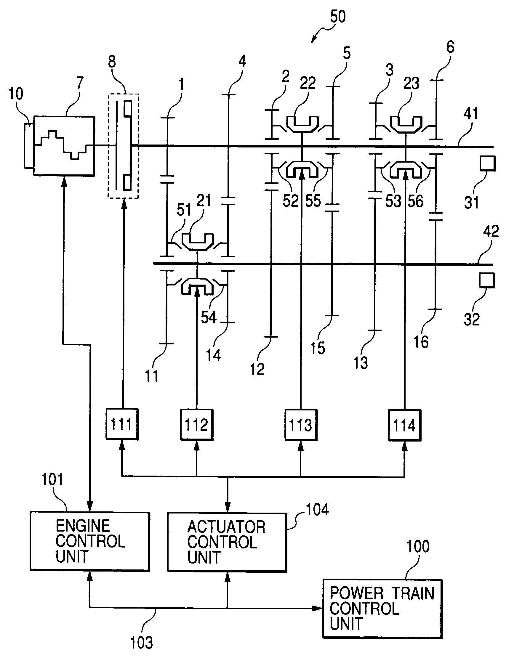
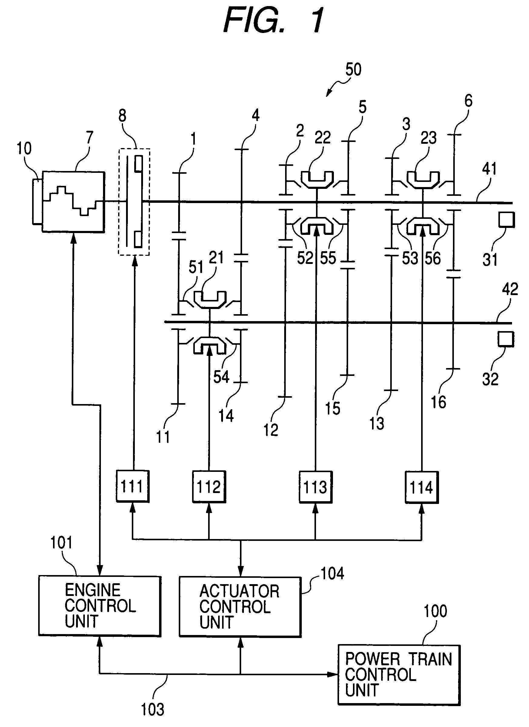
[0033]The constitution and operation of the car control unit according to one embodiment of the present invention will be explained below with reference to FIGS. 1 to 22. Firstly by referring to FIG. 1, the constitution of a car system using the car control unit of this embodiment.

[0034]FIG. 1 is a block diagram of a car system using the car control unit according to one embodiment of the present invention.

[0035]An engine 7 which is a drive power source has an engine speed sensor (not shown in the drawing) for measuring the speed of the engine 7, an electronic throttle 10 for adjusting engine torque, and a fuel injector (not shown in the drawing) for injecting a fuel amount corresponding to the amount of intake air. An engine control unit 101, by operating the amount of intake air, fuel amount, and ignition time, can control the torque of the engine 7 with high precision.

[0036]As a fuel injector, there are an air intake port injection system injecting fuel to an air intake port and ...


PUM


Abstract

A car system and control method in which transmission shifting is controlled such that synchronizer damage is avoided. A state discrimination device detects or infers the state of each frictional surface of the synchronizers. A synchronizer for forming an intermediate transfer path is selected according to a parameter indicating the state of the frictional surface detected or inferred by the state discrimination device. Engine torque control reduces the engine torque according to a parameter indicating the state detected or inferred by the state discrimination device.

Description

BACKGROUND OF THE INVENTION[0001]The present invention relates to a control unit and a control method for a car loading an automatic transmission and more particularly to a control unit and a control method suited to a car including a synchronizer type transmission having a plurality of gears and a plurality of synchronizer capable of transferring torque from the input shaft to the output shaft as an automatic transmission.[0002]Recently, as a system having a clutch and gear change which are automated using a synchronizer type transmission used for a manual transmission, an automated manual transmission (hereinafter referred to as an automatic MT) has been developed. However, under control by a conventional automatic MT for shifting, the drive torque is interrupted by the clutch disengaging and engaging operation, and the shift quality is degraded, and a sense of incompatibility may be given to a crewman.[0003]Therefore, for example, as described in Japanese Laid-open Patent Publica...

Claims


Application Information

Patent Timeline
IPC IPC(8): B60W10/02B60W10/06B60W10/04B60W10/10B60W10/11F02D29/00F16H59/68F16H59/72F16H61/02F16H61/04F16H61/684F16H63/50
CPCB60W10/11B60W30/18F16H61/0403F16H61/0437B60W10/06B60K2741/286Y10T477/6395B60W2510/0291B60W2710/0616F16H61/684F16H63/502F16H2061/0418F16H2061/0425F16H2061/0429F16H2306/42Y10T477/675Y10T477/6403Y10T477/653B60W10/02B60W10/10
Inventor SAKAMOTO, HIROSHIOKADA, TAKASHIMATSUMURA, TETSUOKUMAGAI, TOSHIHARUSUNAGA, ISAMUISHIHARA, SUNAO
Owner HITACHI LTD
Why Eureka
Try Eureka