Check patentability & draft patents in minutes with Patsnap Eureka AI!

Magnetic suspension bearing with damping system

Inactive Publication Date: 2006-05-02
IND TECH RES INST
View PDF11 Cites 17 Cited by
  • Summary
  • Abstract
  • Description
  • Claims
  • Application Information

AI Technical Summary

Benefits of technology

[0008]In view of the aforesaid disadvantages, the primary object of the invention is to provide a magnetic suspension bearing with damping system that has capability to reduce the vibration of the rotor and may be fabricated at a lower cost.
[0011]The magnetic damping device located below the magnetic driving unit. The magnetic damping device has a magnetic unit and a elastic unit. The magnetic unit corresponding to the magnetic driving unit uses to generate magnetic force between them. The elastic unit coupled below the magnetic unit so reduces greatly the vibration of the magnetic unit.

Problems solved by technology

However, its service life is shorter.
The ball bearing has a longer service life, but it is more expensive and has a lower capability to withstand impact.
As a result, the motor tends to generate vibration and noise, and its service life becomes lower.
However, it has starting friction and wearing problem that has yet to be overcome.
Moreover, its production cost is higher, and production yield still does not reach the level desired.
However, the foregoing conventional techniques suit to large scale mechanism.
In other words, it is so complex so that difficult to assemble, and unable apply to the small scale motor which are widely used in various types of electronic products, especially on data storage devices.
However, above-mentioned conventional techniques remain unstable.
That is to say, the motors such as the ball bearing or the sleeve bearing are difficult to prevent from the rotor touching with the stator even with the balancing force between the balance plate and the magnet of the rotor.
Moreover, the efficiency of the dissipation the vibration energy is limited because of lack of damper.
In short, there are still a lot of problems in the conventional techniques remained to be overcome.

Method used


Image

  • Magnetic suspension bearing with damping system
  • Magnetic suspension bearing with damping system
  • Magnetic suspension bearing with damping system

Examples


first embodiment

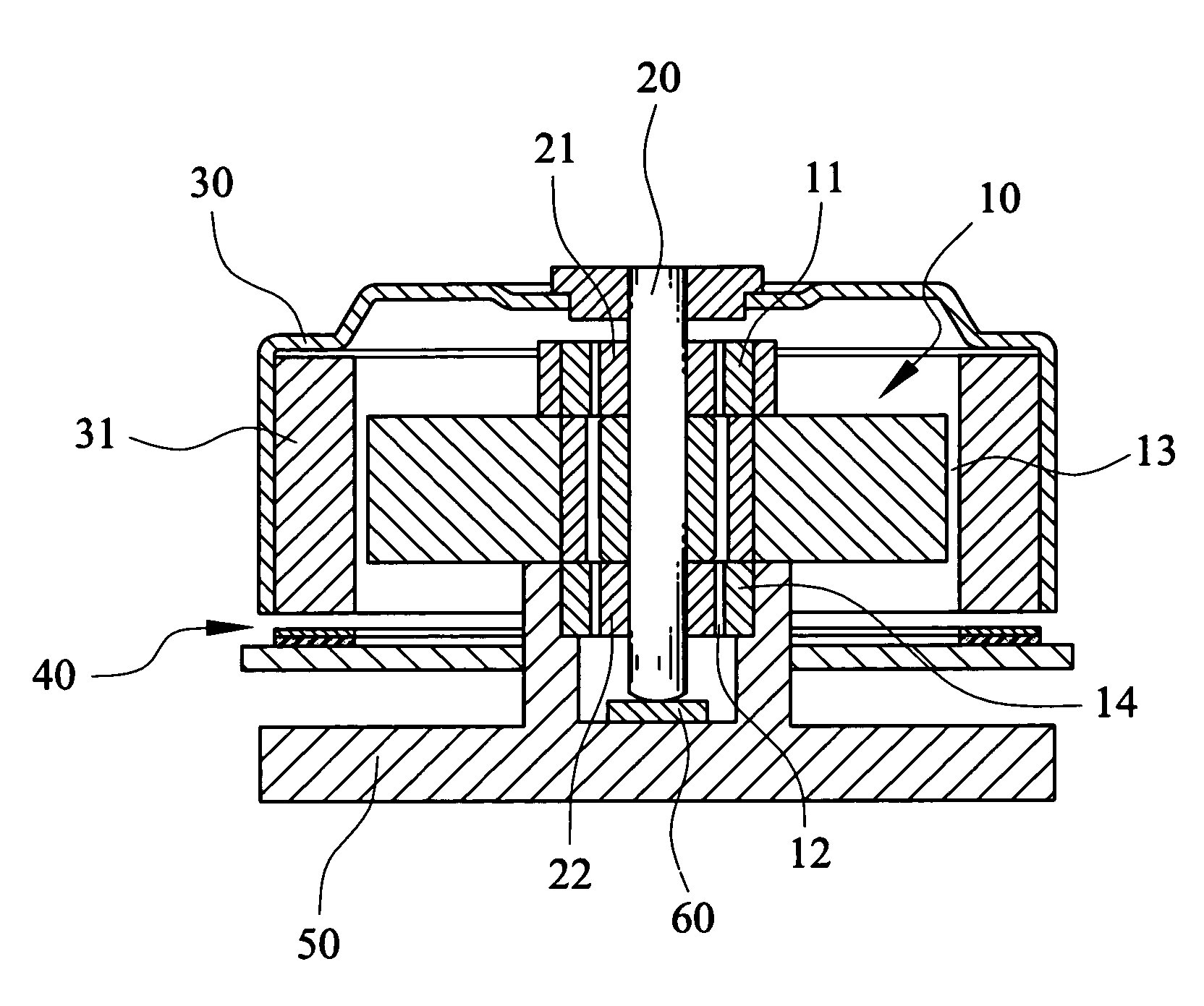
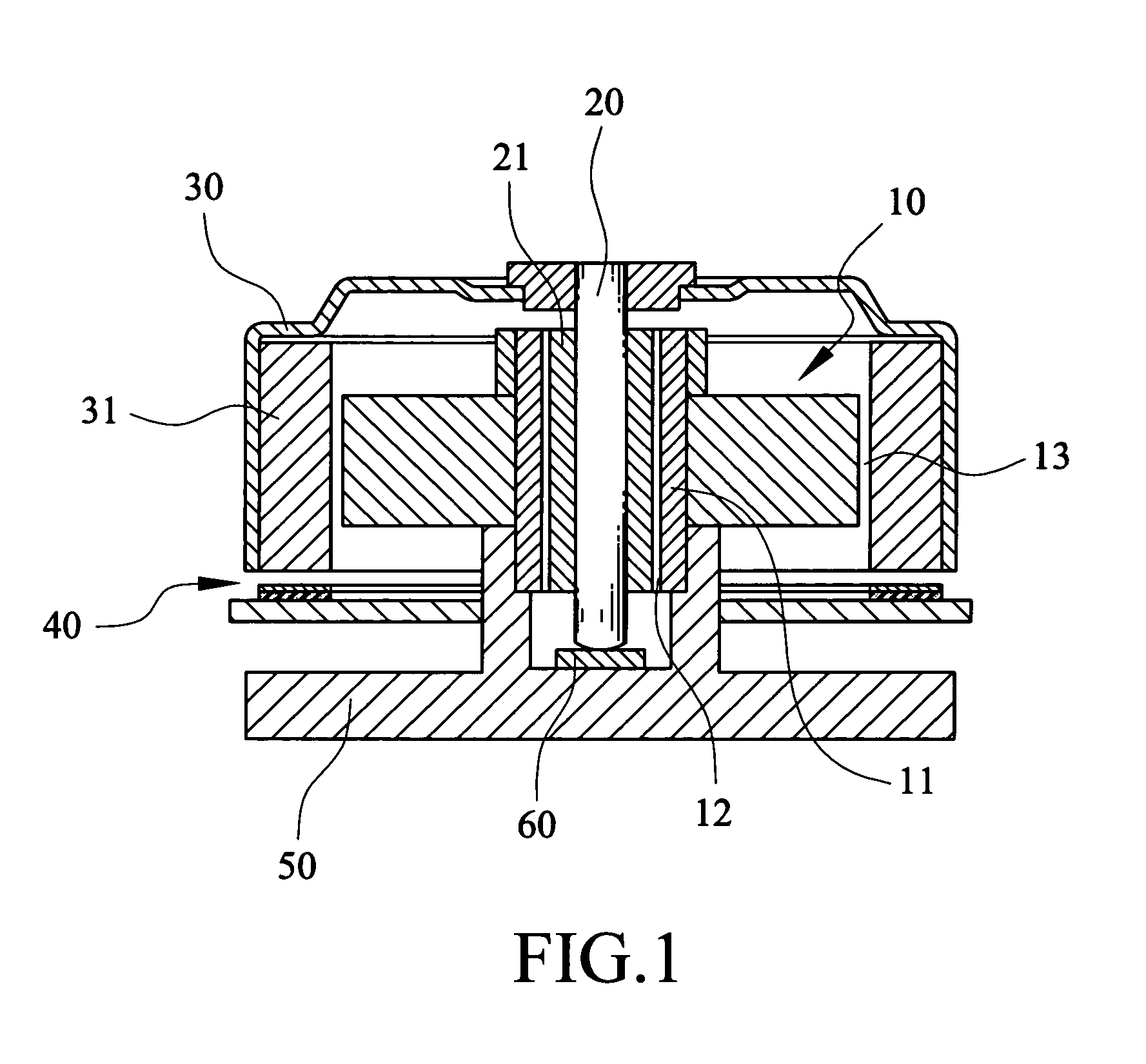
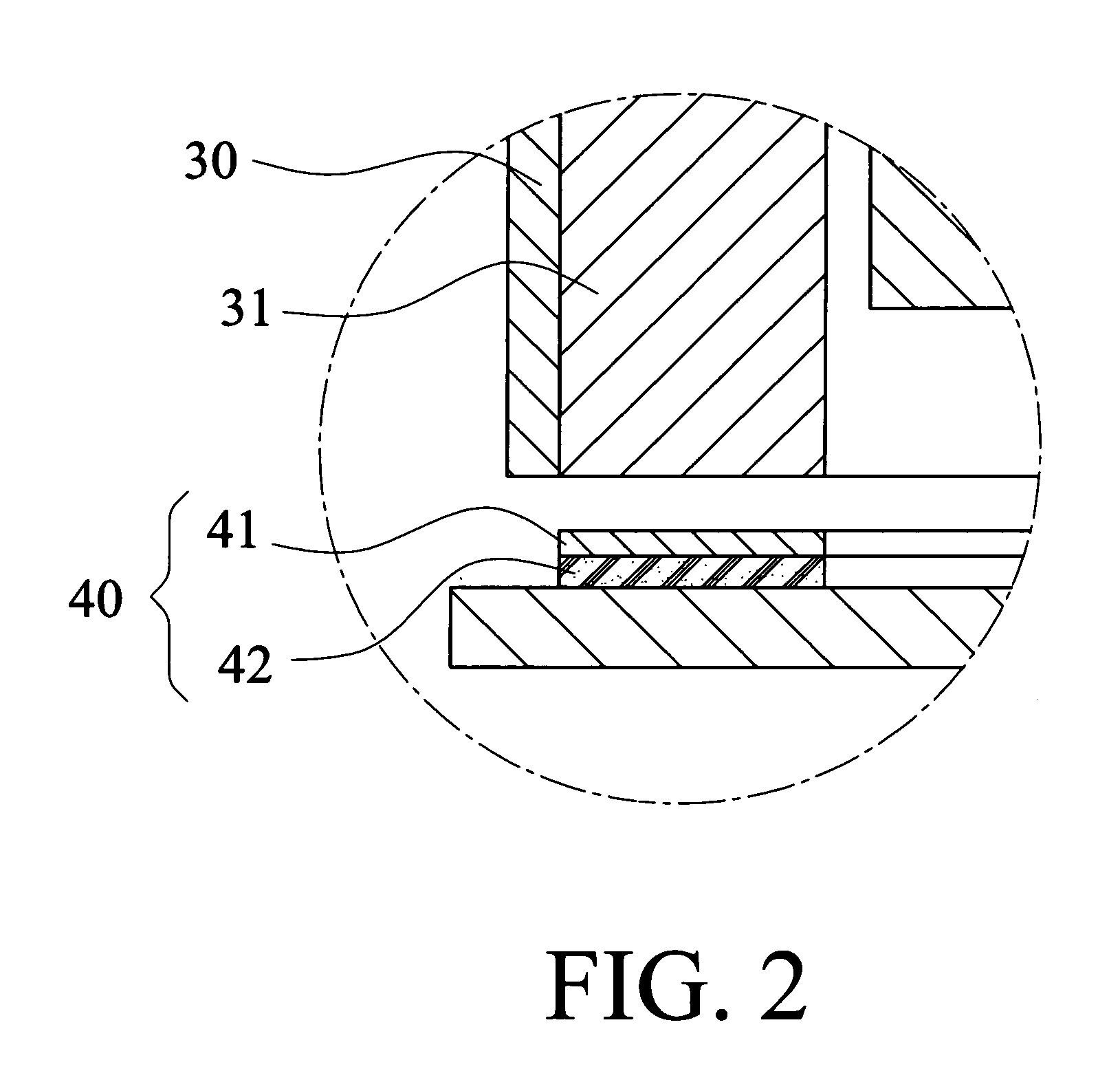
[0022]The magnetic suspension bearing of the invention aims at reducing the vibration of rotor and increase the service life of the product, and to provide a simple magnetic bearing at a low coast. Refer to FIG. 1 for the invention. The invention includes a stator 10, a rotor 20 and a magnetic damping device 40. The stator 10 such as the iron core has an internal portion 12 and an external portion 13, and the rotor 20 may rotatably locate at the internal portion 12. A loading section 60 such as a friction pad installed on base dock 50 locates at the bottom end of the rotor 20 to hold the rotor 20, and the rotor 20 is in contact with the loading section 60 on a single point. A yoke 30 couples with a top end of the rotor 20, and the yoke 30 includes a magnetic driving unit corresponding to the external portion 13 of the stator 10.

[0023]The stator 10 has a stator magnetic unit 11 mounted on the internal portion 12. The rotor 20 includes a rotor magnetic unit 21 corresponding to the sta...

second embodiment

[0028]For further reduce the vibration of the rotor 20, please refer to FIG. 7 for yet another embodiment of the invention. the invention includes a sub stator magnetic unit 14 located on the bottom side of the stator 10, and the stator magnetic unit 11 installed on the top side of the stator 10. Similarly, a sub rotor magnetic unit 22 corresponding to the sub stator magnetic unit mounts on the bottom side of the rotor 20, and the rotor magnetic unit 21 installs on the top side of the rotor 20 corresponding to the stator magnetic unit 11. In addition, refer to FIG. 8, the stator magnetic unit 11 has a magnetic center line B-B′ and the rotor magnetic unit 21 also has a magnetic center line A-A′. The magnetic center line A-A′ is lower than the magnetic center line B-B′ for generating an axial prestressing force to the rotor 20. Likewise, the sub stator magnetic unit 14 has a magnetic center line C-C′ and the sub rotor magnetic unit 22 also has a magnetic center line D-D′. The magnetic...


PUM


Abstract

A magnetic suspension bearing with damping system includes a stator having a stator magnetic unit mounted on the internal portion of the stator, and a rotor rotatably located at the stator. A rotor magnetic unit installed on the rotor corresponding to the stator magnetic. The rotor further has a yoke having a magnetic driving unit corresponding to the external portion of the stator. A magnetic damping device located has a magnetic unit and an elastic unit, wherein the magnetic unit corresponding to the magnetic driving unit generates magnetic force between them, and the elastic unit coupled below the magnetic unit uses to reduce the vibration of the magnetic unit for maintaining the rotation of the rotor smooth and steady.

Description

FIELD OF THE INVENTION[0001]The invention relates to a magnetic suspension bearing, and more particularly to a magnetic suspension bearing with damping system that can greatly reduce the vibration of the rotor, and is simple and low in cost.BACKGROUND OF THE INVENTION[0002]In recent years rapid innovations and developments have occurred with electronic products. With the continuous advance of semiconductor manufacturing technologies, electronic products have become more powerful and their prices have dropped. They are now widely accepted by the general public. Nowadays there are a wide variety of electronic products on the market. For the driving motor bearings used in information storage devices, there are oil impregnated bearings, ball bearings, and the like. The oil impregnated bearing has a lower price and thus cost advantage. However, its service life is shorter. The ball bearing has a longer service life, but it is more expensive and has a lower capability to withstand impact....

Claims


Application Information

Patent Timeline
IPC IPC(8): H02K7/09
CPCH02K7/09F16C39/063F16C32/0406
Inventor WANG, CHIEN-CHANGTUNG, PI-CHENGXIAO, REN-BINCHEN, WEI-CHENGLIU, CHIEN-SHENGCHANG, YU-HSIUHUANG, DER-RAY
Owner IND TECH RES INST
Features
  • R&D
  • Intellectual Property
  • Life Sciences
  • Materials
  • Tech Scout
  • Unparalleled Data Quality
  • Higher Quality Content
  • 60% Fewer Hallucinations
Learn More