
Termination block

a technology of termination blocks and termination blocks, which is applied in the direction of coupling device details, substation equipment, coupling device connections, etc., can solve the problems of less reliable, more expensive and laborious than desired, and undesirable costs incurred in the construction of conventional termination blocks

Inactive Publication Date: 2006-05-02
LEVITON MFG
View PDF4 Cites 5 Cited by
  • Summary
  • Abstract
  • Description
  • Claims
  • Application Information

AI Technical Summary

Benefits of technology

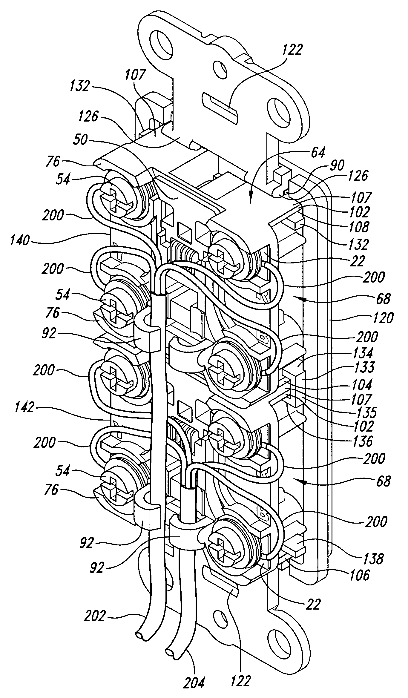
[0012]The termination block may also include a plurality of forwardly projecting front support members. The front support members are positioned to engage at least a portion of the rear raised portions of another termination block when two termination blocks are positioned in engagement with the front face toward the rear face of the another termination block. The combined length of the front support members and the portions of the rear raised portions in engagement are sufficient to keep the front face from contacting the rear face of the another termination block, whereby damage to the screws is prevented during face to face shipment or storage of the termination blocks.
[0018]A screw retainer extends rearward from the rear face and is sized to removably retain a mounting screw used to mount a mounting member to which the termination block is attached. The screw retainer is sized to retain a wire cable having wires to be connected to the terminal connection pads when the mounting screw is removed therefrom to serve as a cable strain relief.

Problems solved by technology

Unfortunately, construction of conventional termination blocks is more expensive and less reliable than desired.
Also, since so many parts are involved, very extensive testing is required for each assembled termination block, which further adds to the inconvenience of construction resulting in undesirable costs being incurred.

Method used


Image

  • Termination block
  • Termination block
  • Termination block

Examples


Embodiment Construction

[0044]As will be discussed in greater detail herein, a termination block 2, shown fully assembled in FIG. 9, is disclosed that greatly reduces the number of individual parts required with conventional termination blocks, thus reducing the manufacturing cost of the termination block and increasing reliability. Other advantages of the termination block 2 will be described.

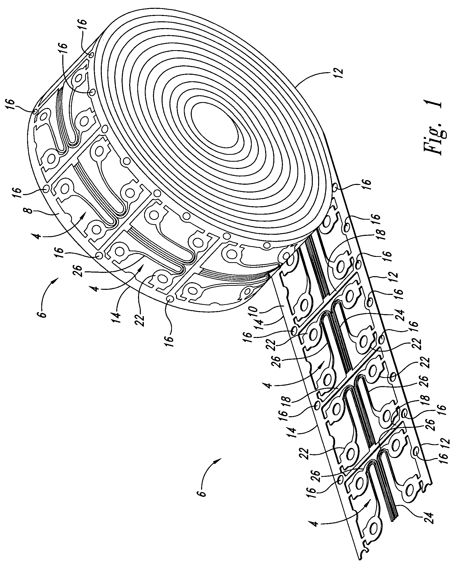
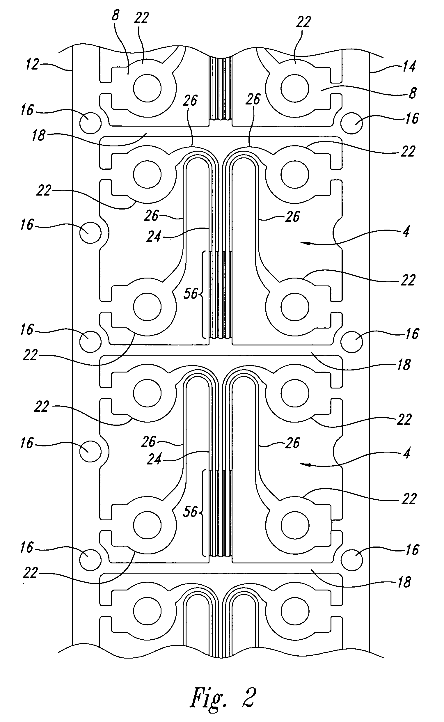
[0045]The termination block 2 is manufactured using a stamped, thin, flat lead frame 4 detached from a roll 6 of continuous strip lead frames, shown in FIG. 1 partially unrolled. Several of the unrolled lead frames 4 are shown with a flat front face surface 8 (facing downward in FIG. 1) and a flat rear face surface 10 (facing upward in FIG. 1). The individual lead frames 4 are positioned between and attached to left and right side edge strips 12 and 14, respectively, of the roll 6. Each of the left and right side edge strips 12 and 14 include a series of sprocket holes 16.

[0046]As is conventional, the sprocket holes ...


PUM


Abstract

A termination block having spaced apart rear and front faces with rear and front apertures, respectively, and a plurality of mounting surfaces on the rear face. A screw receiving portion receiving a screw is positioned at each mounting surface. An interior recess is between the rear and front faces, accessible from the rear and front faces through the rear and front apertures. A terminal connection pad is positioned at the rear face at each mounting surface, and a plurality of tines extend through the rear aperture and are positioned within the interior recess for access through the front aperture. Each tine has a flat contact end portion. A plurality of trace members positioned at the rear face, each electrically coupling together one of the terminal connection pads and one of the tines. The terminal connection pads, tines and trace members are formed as part of a stamped, thin, flat lead frame.

Description

BACKGROUND OF THE INVENTION[0001]1. Field of the Invention[0002]The present invention is directed generally to communication interface equipment and, more particularly, to termination blocks for connecting systems for telephone networks.[0003]2. Description of the Related Art[0004]Termination blocks are used to quickly connect telephonic devices, such as telephones, to telephone networks. A termination block provides a multi-wire connector jack, having multiple tines, to receive a multi-wire connector plug having multiple tines such that contact is made between the corresponding pairs of plug and jack tines when the connector plug is inserted into the connector jack. The jack tines are connected by wires to termination screws to which the wires of a telephone network are also connected.[0005]The multi-wire connector plug is typically connected to a phone cord having two, four, or more wires by making connections between the corresponding pair or pairs of phone cord wires and plug ti...

Claims


Application Information

Patent Timeline
Patent Type & Authority Patents(United States)
IPC IPC(8): H04M9/00H01R9/24H01R4/34H01R13/58H01R13/74H01R24/58H01R25/00H04M1/00H04M1/02
CPCH01R4/34H01R13/58H01R24/64H01R25/006H04M1/0293H01R13/748H01R9/24
Inventor ZIELKE, DARRELL W.NELSON, AUBREY D.
Owner LEVITON MFG
Learn More