Method for determining a position of a robot

a robot and position technology, applied in the field of robot position determination, can solve the problems of non-conformity, damage to the substrate or yield loss due to non-conformity, and the methodology of increasing the accuracy of the robot generally does not compensate for thermal expansion and contraction experienced

Inactive Publication Date: 2006-05-02
APPLIED MATERIALS INC
View PDF22 Cites 78 Cited by
  • Summary
  • Abstract
  • Description
  • Claims
  • Application Information

AI Technical Summary

Problems solved by technology

Accordingly, damage to the substrate or yield loss due to non-conformity because of substrate misalignment is highly undesirable.
However, these methodologies for increasing the accuracy of the robot generally do not compensate for thermal expansion and contraction experienced by the robot as heat is transferred to the robot from hot wafers and from hot surfaces within the process chambers.
As evolving process technology has led to higher operating temperatures for many processes, transfer robots are increasingly exposed to high temperatures.
Due to the increase thermal exposure of transfer robots, the increase in robot linkage lengths and reach distances, it has become evident that robotic thermal expansion now substantially contributes to substrate misplacement.
This increase in thermal energy generally causes the linkages to expand, thus shifting the center reference position of the blade without providing feedback to the robot's controller.
Cooling the robot linkages creates a similar problem by causing the linkages to shorten as they cool.
Thus, the substrate may be misposi...

Method used


Image

  • Method for determining a position of a robot
  • Method for determining a position of a robot
  • Method for determining a position of a robot

Examples


Embodiment Construction

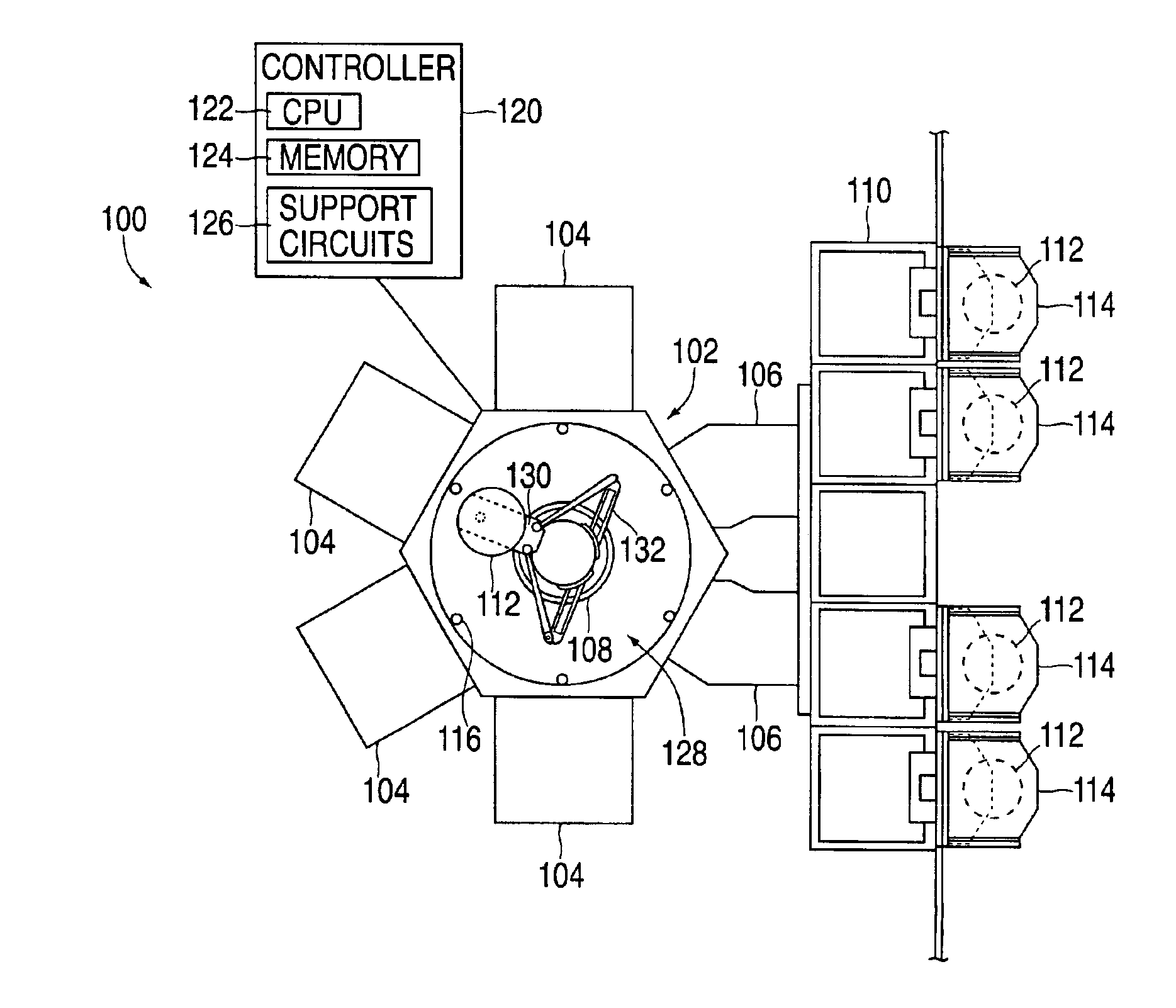
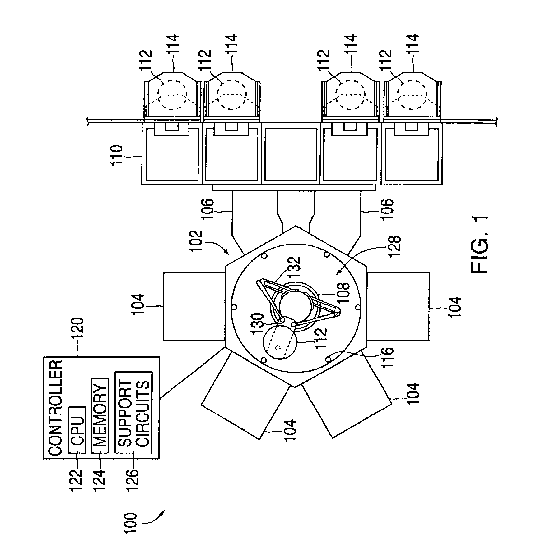
[0024]FIG. 1 depicts one embodiment of a semiconductor processing system 100 wherein a method for determining a position of a robot 108 may be practiced. The exemplary processing system 100 generally includes a transfer chamber 102 circumscribed by one or more process chambers 104, a factory interface 110 and one or more load lock chambers 106. The load lock chambers 106 are generally disposed between the transfer chamber 102 and the factory interface 110 to facilitate substrate transfer between a vacuum environment maintained in the transfer chamber 102 and a substantially ambient environment maintained in the factory interface 110. One example of a processing system which may be adapted to benefit from the invention is a CENTURA® processing platform available from Applied Materials, Inc., of Santa Clara, Calif. Although the method for determining the position of a robot is described with reference to the exemplary processing system 100, the description is one of illustration and a...


PUM

PropertyMeasurementUnit
Lengthaaaaaaaaaa
Velocityaaaaaaaaaa
Thermal expansion coefficientaaaaaaaaaa

Abstract

Generally, a method of determining a position of a robot is provided. In one embodiment, a method of determining a position of a robot comprises acquiring a first set of positional metrics, acquiring a second set of positional metrics and resolving the position of the robot due to thermal expansion using the first set and the second set of positional metrics. Acquiring the first and second set of positional metrics may occur at the same location within a processing system, or may occur at different locations. For example, in another embodiment, the method may comprise acquiring a first set of positional metrics at a first location proximate a processing chamber and acquiring a second set of positional metrics in another location. In another embodiment, substrate center information is corrected using the determined position of the robot.

Description

CROSS-REFERENCE TO RELATED APPLICATIONS[0001]This application claims the benefit of prior, co-pending U.S. patent application Ser. No. 09 / 905,091, filed Jul. 12, 2001, which is herein incorporated by reference.BACKGROUND OF THE INVENTION[0002]1. Field of the Invention[0003]The embodiments of the invention generally relate to a method for determining a reference position of a robot utilized in a semiconductor processing system.[0004]2. Background of the Related Art[0005]Semiconductor substrate processing is typically performed by subjecting a substrate to a plurality of sequential processes to create devices, conductors and insulators on the substrate. These processes are generally performed in a process chamber configured to perform a single step of the production process. In order to efficiently complete the entire sequence of processing steps, a number of process chambers are typically coupled to a central transfer chamber that houses a robot to facilitate transfer of the substrat...

Claims


Application Information

Patent Timeline
IPC IPC(8): G05B15/00G05B19/00B25J9/00B25J9/10G05B19/404G06F19/00H01L21/00H01L21/68
CPCB25J9/0009B25J9/107G05B19/404H01L21/67259H01L21/67742H01L21/67748H01L21/68G05B2219/37608G05B2219/39192G05B2219/49169Y10S414/139Y10S414/137Y10S414/136G05B2219/49207
Inventor FREEMAN, MARVIN L.HUDGENS, JEFFREY C.COX, DAMON KEITHPENCIS, CHRIS HOLTRICE, MICHAELVAN GOGH, DAVID A.
Owner APPLIED MATERIALS INC
Why Eureka
Try Eureka