
Method for detecting leak before rupture in a pipeline

a pipeline and leak detection technology, applied in the direction of mechanical measurement arrangements, mechanical roughness/irregularity measurements, instruments, etc., can solve the problems of pipeline leakage, external stress corrosion cracking (scc), and cracking or cracking fields that can initiate and grow

Inactive Publication Date: 2006-05-02
GENERAL ELECTRIC CO
View PDF1 Cites 6 Cited by
  • Summary
  • Abstract
  • Description
  • Claims
  • Application Information

AI Technical Summary

Benefits of technology

"The patent describes a method for detecting leaks in pipelines before they become too big and cause damage. The method involves analyzing cracks in the material using a special assessment chart and then using a technique called ductile tearing to determine if the crack is stable or unstable. This helps to identify which cracks are likely to cause damage and which ones can be left alone. This method can help to prevent leaks and reduce damage to pipelines."

Problems solved by technology

Cracks or crack fields can initiate and grow in a pipeline by stress corrosion cracking, fatigue, or corrosion fatigue.
The pipeline leaks if one of the cracks penetrates through the wall.
The first incident of external stress corrosion cracking (SCC) on natural gas pipelines occurred in the mid 1960's and hundreds of failures have occurred since that time.
Since these procedures only predict crack initiation rather than a catastrophic failure for materials that exhibit stable crack growth by ductile tearing, the results are inconsistent with leak incidents observed in the field.
However, the FAD procedures for critical size analysis, i.e., the largest acceptable crack size, in API 579 is not consistent with crack initiation criteria in references such as, I. Milne, R. A. Ainsworth, A. R. Dowling and A. T. Stewart: “Assessment of integrity of structures containing defects”, CEGB report R / H / R6—Revision 3, 1986; and M. Janssen, J. Zuidema and R. J. H. Wanhill: “Elastic-Plastic fracture mechanics”, Fracture Mechanics, Part III, Chapter 8, pp.
For materials exhibiting significantly ductile tearing prior to failure, prediction of leak or rupture conditions is conservative and does not provide consistent results with field observed “leak-before rupture” incidents.
This is because the resulting increase in toughness involved during crack growth is not taken into account in the analysis.

Method used


Image

  • Method for detecting leak before rupture in a pipeline
  • Method for detecting leak before rupture in a pipeline
  • Method for detecting leak before rupture in a pipeline

Examples


Embodiment Construction

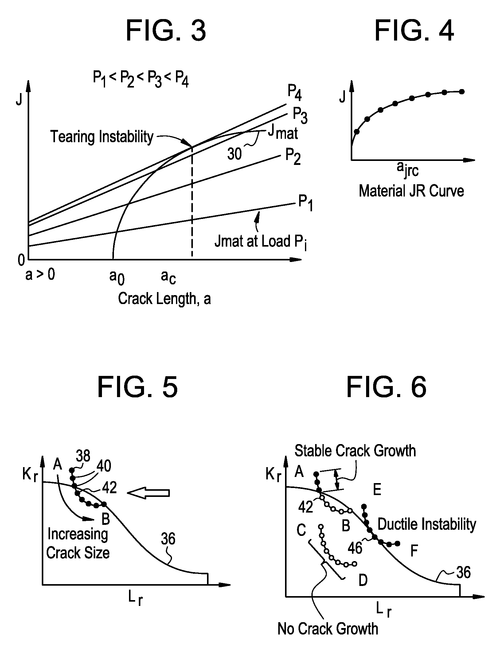
[0024]The acceptance criteria for a crack-containing structure in accordance with the API 579 assessment procedures and associated assessment procedures, such as, R6 and BS 7910, is analyzed against the initiation of crack extension rather than crack instability (rupture). Since ductile materials in a plane stress loading condition (e.g., thin wall for linepipe ferrite steels on the upper shelf of a ductile-brittle transition curve) often exhibit extensive plastic deformation prior to rupture, the assessment methodology in such a case can be extremely conservative and may not be appropriate for predicting actual failure conditions like leak-before-rupture.

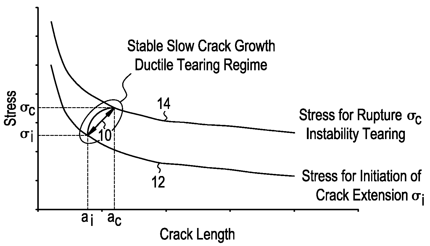
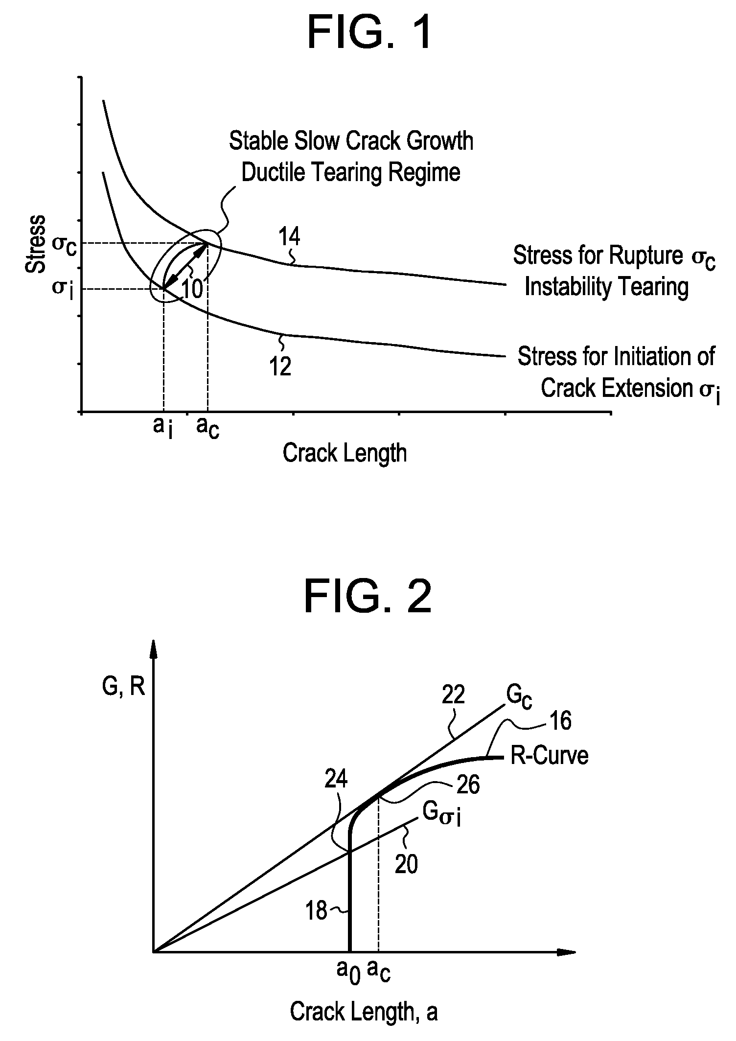
[0025]To develop a tearing instability model for leak-before-rupture assessment, the ductile tearing and tearing instability process is reviewed. This process is graphically illustrated in FIG. 1, where a crack with an initial length a begins to extend at αi (e.g., initiation of crack growth) at a certain stress σi If the stress is...


PUM


Abstract

A method for leak-before-rupture assessment including using a failure assessment diagram (FAD) assessment curve from a crack initiation based FAD analysis to analyze a crack in a material; and using a ductile tearing analysis in conjunction with the FAD assessment curve to detect a crack exhibiting at least one of ductile tearing stability and tearing instability prone to rupture during growth of the crack.

Description

BACKGROUND OF THE INVENTION[0001]This invention relates to a method for detecting a leak before rupture, and more particularly, relates to a method for detecting a leak before rupture using a tearing instability approach in pipeline applications.[0002]Cracks or crack fields can initiate and grow in a pipeline by stress corrosion cracking, fatigue, or corrosion fatigue. The pipeline leaks if one of the cracks penetrates through the wall. The prompt detection of the leak can serve as an early warning and remedial actions can be taken to avoid a subsequent catastrophic failure. It is practically important, therefore, to develop analysis methods that predict conditions for a “leak-before-rupture”.[0003]The first incident of external stress corrosion cracking (SCC) on natural gas pipelines occurred in the mid 1960's and hundreds of failures have occurred since that time. Stress corrosion cracking (SCC) is the formation of brittle cracks in a normally sound material through the simultaneo...

Claims


Application Information

Patent Timeline
Patent Type & Authority Patents(United States)
IPC IPC(8): G01B3/34G01B5/28
CPCG01N3/28G01N2203/0064G01N2203/0274G01N2203/0218G01N2203/0066
Inventor GAO, MINGLIMON, SERGIO
Owner GENERAL ELECTRIC CO
Learn More