Laser centering device

a laser centering device and laser technology, applied in the direction of surveying plumb lines, angle measurement, instruments, etc., can solve the problems of inconvenient laser centering device, and large burden on the operator for installing survey equipment on an inclined si

Inactive Publication Date: 2006-05-09
SOKKOIA COMPANY LIMITED
View PDF25 Cites 16 Cited by
  • Summary
  • Abstract
  • Description
  • Claims
  • Application Information

AI Technical Summary

Benefits of technology

[0012]In order to solve the above-described problems, the laser centering device according to the invention includes a prism fixed at one end thereof and is internally provided with a laser beam source, wherein the laser centering device is mounted to a survey apparatus in which positional adjustment in the axial direction and angular adjustment around the axis are enabled.

Problems solved by technology

However, since the centering telescope optical system is located at a lower position than that of a collimation telescope used for measurement, the operator looks into the optical system in a half-sitting posture (in a squatted state), which creates a burden on the operator.
In particular, work for installing a survey apparatus on an inclined site becomes a large burden on an operator.
However, for work in bright sunlight, the laser centering device is inconvenient in that it is difficult to see the laser spot.
Although a survey apparatus provided with both a centering telescope optical system and a laser centering device as shown in FIG. 6 is desirable, there is a problem in that the apparatus becomes complicated and becomes expensive.
However, if, in a laser centering device as shown in FIG. 6, there is an error in the attaching position and angle of the laser beam source 3 and reflection portion 61, a centering error occurs.
In particular, even if an error in the angle of the reflection portion 61 is only slight, the position of the laser spot largely changes due to a principle of the optical lever, wherein there is a problem in that a large centering error occurs.
However, adjustment of the emission direction of the laser beam requires various steps of adjustment for each of the many components such as the laser beam source 3, reflection portion 61, etc., and it is very cumbersome.

Method used


Image

  • Laser centering device
  • Laser centering device
  • Laser centering device

Examples


first embodiment

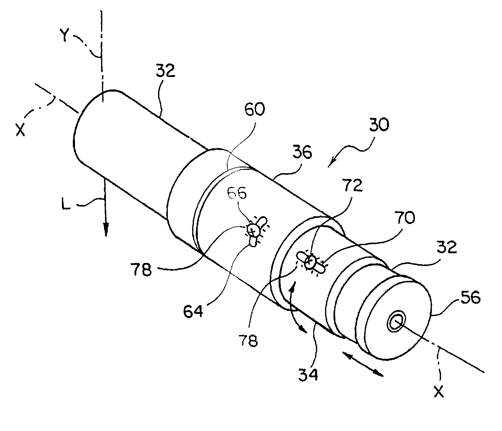
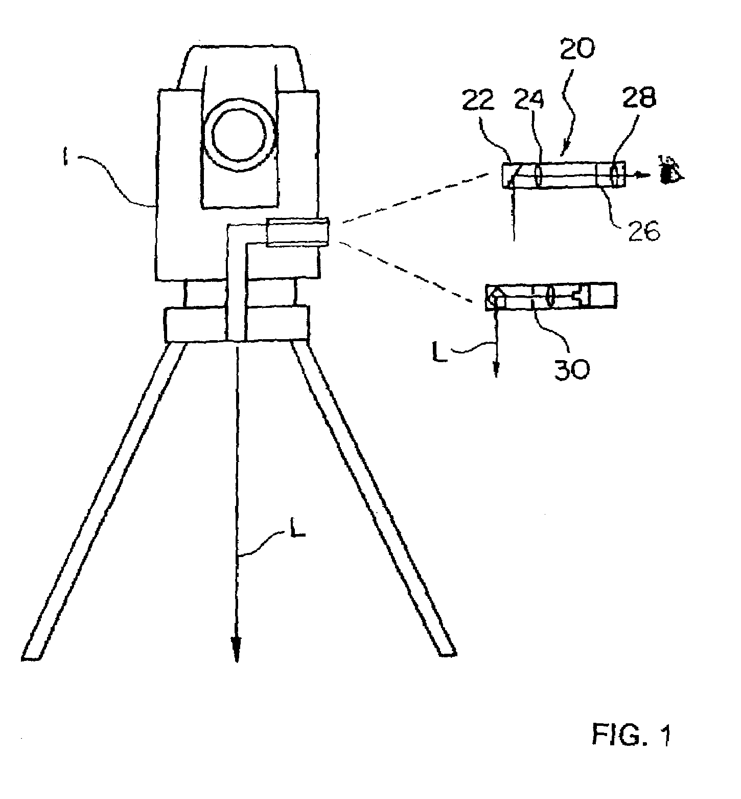
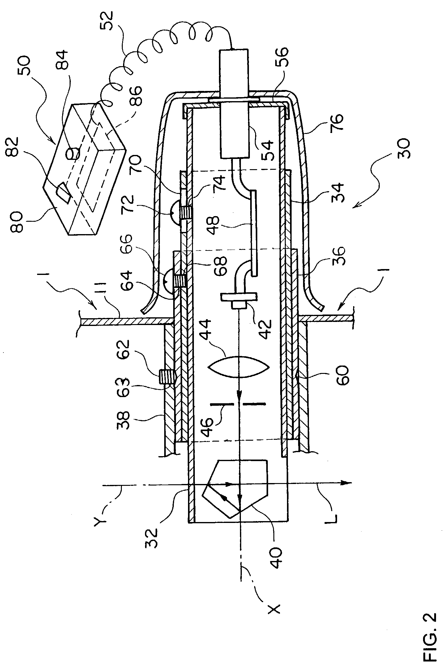
[0028]Therefore, a detailed description is given of a laser centering device 30 according to the invention with reference to a sectional view shown in FIG. 2 and a perspective view shown in FIG. 3. The laser centering device 30 includes an inner barrel 32, an intermediate barrel 34 having the inner barrel 32 fixed so as to adjust the position thereof in the axial direction, and an outer barrel 36 having the intermediate barrel 34 fixed so as to adjust the angle thereof around the axis X, wherein the outer barrel 36 is fixed at the fixing portion 38 (lower body cover) of the centering telescope optical system of the survey apparatus 1.

[0029]A laser diode 42 which is a visible laser beam source for emitting a laser beam L, a collimation lens 44 that collimates the laser beam emitted from the laser diode 42, an aperture 46 for stopping down the laser beam L, and a printed circuit board 48 for controlling the light emission of the laser diode 42 are fixed in the vicinity of the center o...

second embodiment

[0050]However, the present invention is not limited to the above-described embodiments, but may be subjected to various modifications. For example, (1) the laser centering device 30 may be formed of only the inner barrel 32, and the inner barrel 32 may be simply fixed at the portion 28 for simply fixing the fixing portion 28 of the centering device telescope optical system so that both positional adjustment in the direction of the axis X and angular adjustment around the axis X are enabled. (2) a Dachprisma 22 that is common to the centering telescope optical system 20 may be used instead of the pentagonal prism 40. (3) the slot 64 extending in the circumferential direction is provided in the outer barrel 36, and the slot 70 extending in the direction of the axis X is provided in the intermediate barrel 34. However, on the contrary, a slot extending in the direction of the axis X may be provided in the outer barrel 36, and a slot extending in the circumferential direction may be pro...


PUM


Abstract

A laser centering device (30) that is attached to a survey apparatus by replacing it with a centering telescope optical system is formed of an inner barrel (32) that fixes a pentagonal prism (40) at one end thereof and is internally provided with a laser beam source (42), an intermediate barrel (34) that moves the inner barrel in the axial direction and fixes it so as to adjust the position thereof, and an outer barrel (36) that turns the intermediate barrel around the axis and fixes it so as to adjust the angle thereof, and at the same time, is fixed at the portion (38) for fixing the centering telescope optical system of the survey apparatus (1). The invention provides a laser centering device for which the emission direction of a laser beam is simply adjusted.

Description

TECHNICAL FIELD OF THE INVENTION[0001]The present invention relates to a laser centering device that is replaceable in a survey apparatus having a centering telescope optical system.BACKGROUND OF THE INVENTION[0002]A prior art survey apparatus has been generally provided with a centering telescope optical system (centering telescope), and has utilized a centering telescope optical system when deploying a survey apparatus directly above a point of measurement. The centering telescope optical system is able to carry out an accurate centering operation because an operator looks directly into the centering telescope optical system. However, since the centering telescope optical system is located at a lower position than that of a collimation telescope used for measurement, the operator looks into the optical system in a half-sitting posture (in a squatted state), which creates a burden on the operator. In particular, work for installing a survey apparatus on an inclined site becomes a l...

Claims


Application Information

Patent Timeline
Patent Type & Authority Patents(United States)
IPC IPC(8): G01C1/00G01C15/00
CPCG01C15/002Y10S33/21
Inventor SAWAGUCHI, SIGEYUKI
Owner SOKKOIA COMPANY LIMITED
Why Eureka
Try Eureka