

Rake with four-wheel stabilizing system
a stabilizing system and rake technology, applied in the direction of rakes, drags, agricultural tools and machines, etc., can solve the problems of not being satisfied, direct rake behind the rake, and system not fully compensating for the motion of the rak
- Summary
- Abstract
- Description
- Claims
- Application Information
AI Technical Summary
Benefits of technology
Problems solved by technology
Method used
Image

Examples
Embodiment Construction
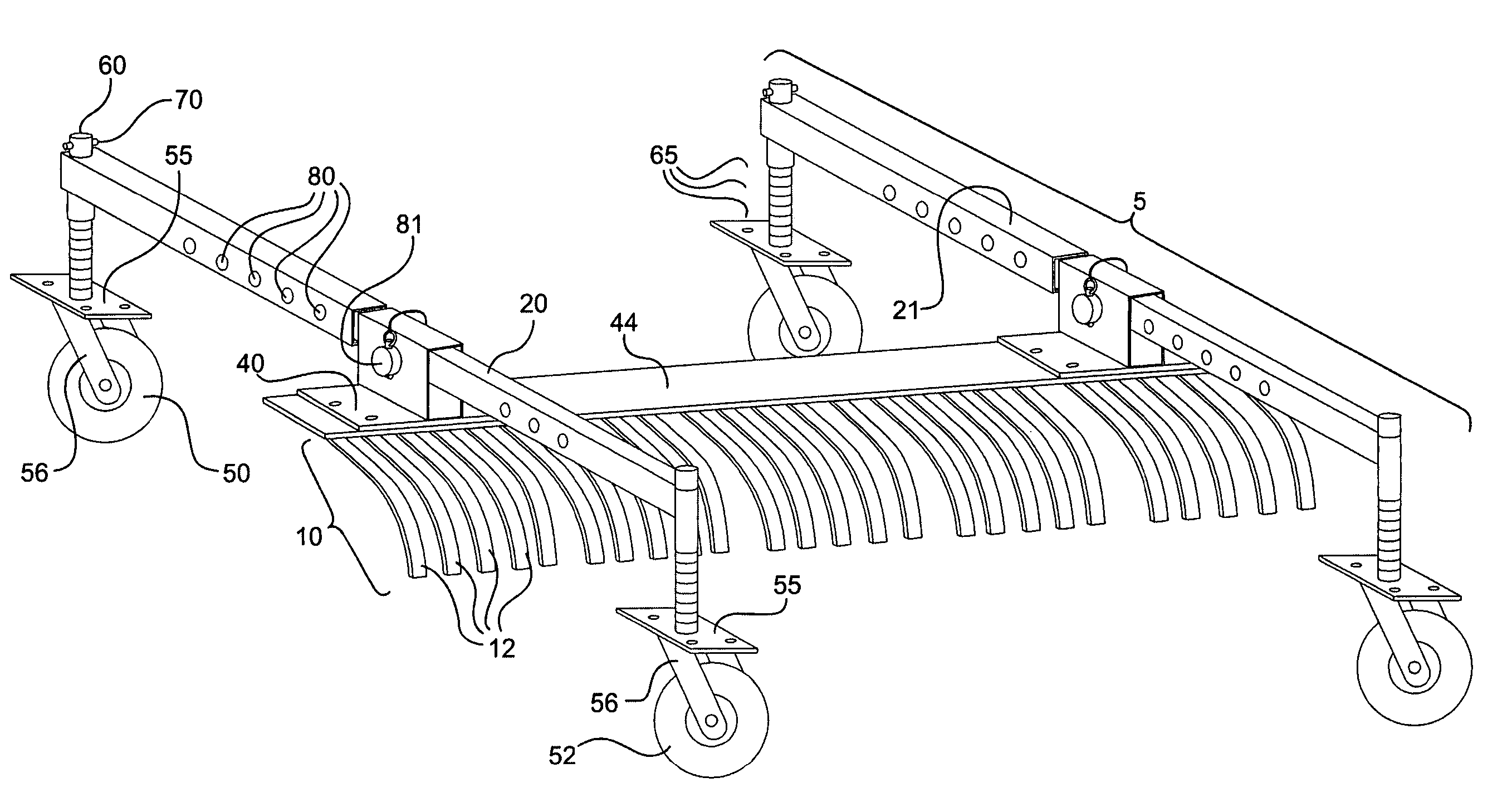
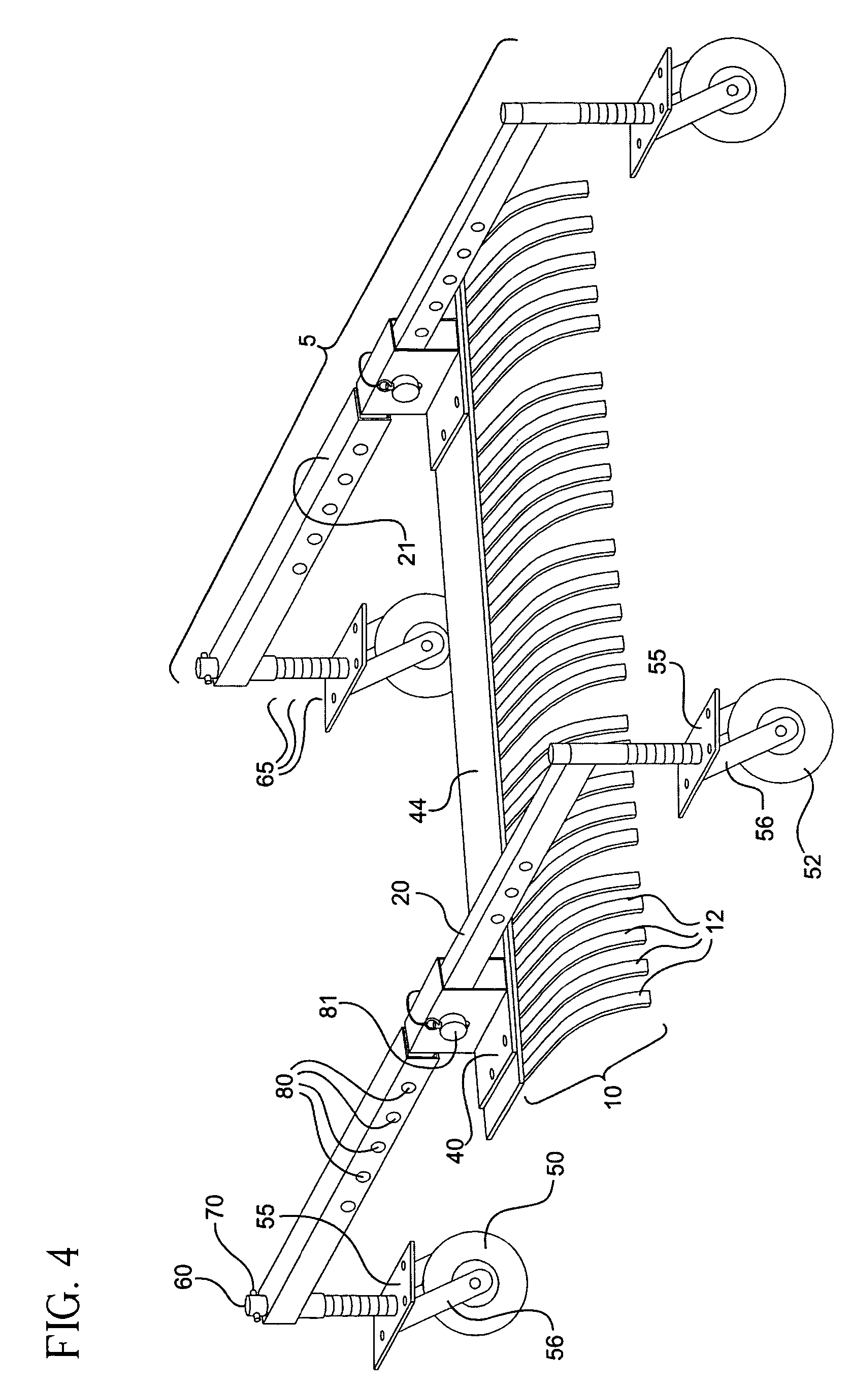
[0025]Looking now at the drawings, some preferred aspects of the invention are described. FIG. 4 shows a rear perspective view of a preferred embodiment of the present invention. The invention comprises two side members 5, each side member adapted to be mounted to a side of, and perpendicularly to, a rake 10. Rake 10 may be a commercially available rake. Typically, rake 10 will include a rigid cross brace 44 having mounting holes or attachment hardware near either end thereof. The rake includes a plurality of curved tines 12 attached to and extending below cross brace 44.
[0026]When the side members 5 are securely mounted to either side of the rake 10, the assembly forms a rigid H-shaped frame or rack. The rake 10 may, but need not, be mounted near the mid-points of the side members. In some cases, an “off center” mounting position provides advantages. For example, in the embodiment shown in FIG. 4, the rake is mounted toward the rear. This provides additional room in front of the ra...
PUM
 Abstract
Description
Claims
Application Information