Check patentability & draft patents in minutes with Patsnap Eureka AI!

Shield tunneling method and shield tunneling machine

a shield tunneling and shield tunneling technology, applied in the direction of shaft equipment, shaft lining, snow cleaning, etc., can solve the problems of restricting ground and inability to effect long-distance tunneling, and achieve the effect of stable tunneling

Inactive Publication Date: 2006-05-09
TAISEI CORP +1
View PDF20 Cites 5 Cited by
  • Summary
  • Abstract
  • Description
  • Claims
  • Application Information

AI Technical Summary

Benefits of technology

[0161]According to the invention, a cutter device, which is of a face plate type, can be contracted into a size accommodable in a turnable body, the turnable body with the cutter device accommodated therein being turned about an axis perpendicular to an axis of the shield body so as to direct the cutter device backward for replacement of damaged bits on the cutter device backward in a dry environment, ensuring safe and efficient replacement of the bits. Long-distant tunneling can be therefore effected to various grounds, using such face plate type cutter device with damaged bits thereon being replaced halfway of tunneling.

Problems solved by technology

This greatly restricts grounds which may be tunneled by a conventional shield tunneling machine with a rotary shield device.
Thus, a conventional shield tunneling machine with a rotary shield device has a drawback that, for grounds which require tunneling with a face plate type cutter device, it cannot effect long-distance tunneling with damaged bits on a cutter device being replaced halfway of tunneling.

Method used


Image

  • Shield tunneling method and shield tunneling machine
  • Shield tunneling method and shield tunneling machine
  • Shield tunneling method and shield tunneling machine

Examples


first embodiment

[0067]FIGS. 4 and 5 show a shield tunneling machine according to the invention in which a shield body 1 is illustrated to have a single skin plate 7; of course, it may alternatively have rear and front skin plates bendable at their connection just like the shield body 1 shown in FIG. 1. It is to be understood that the invention may have any type of shield body provided that a skin plate or plates have therein a turnable body in which an excavating drive is accommodated. The description will be made on the turnable body in the form of sphere; however, the turnable body may be of any shape such as a cylinder or a tube with a polygonal contour provided that it is turnable perpendicularly of the skin plate.

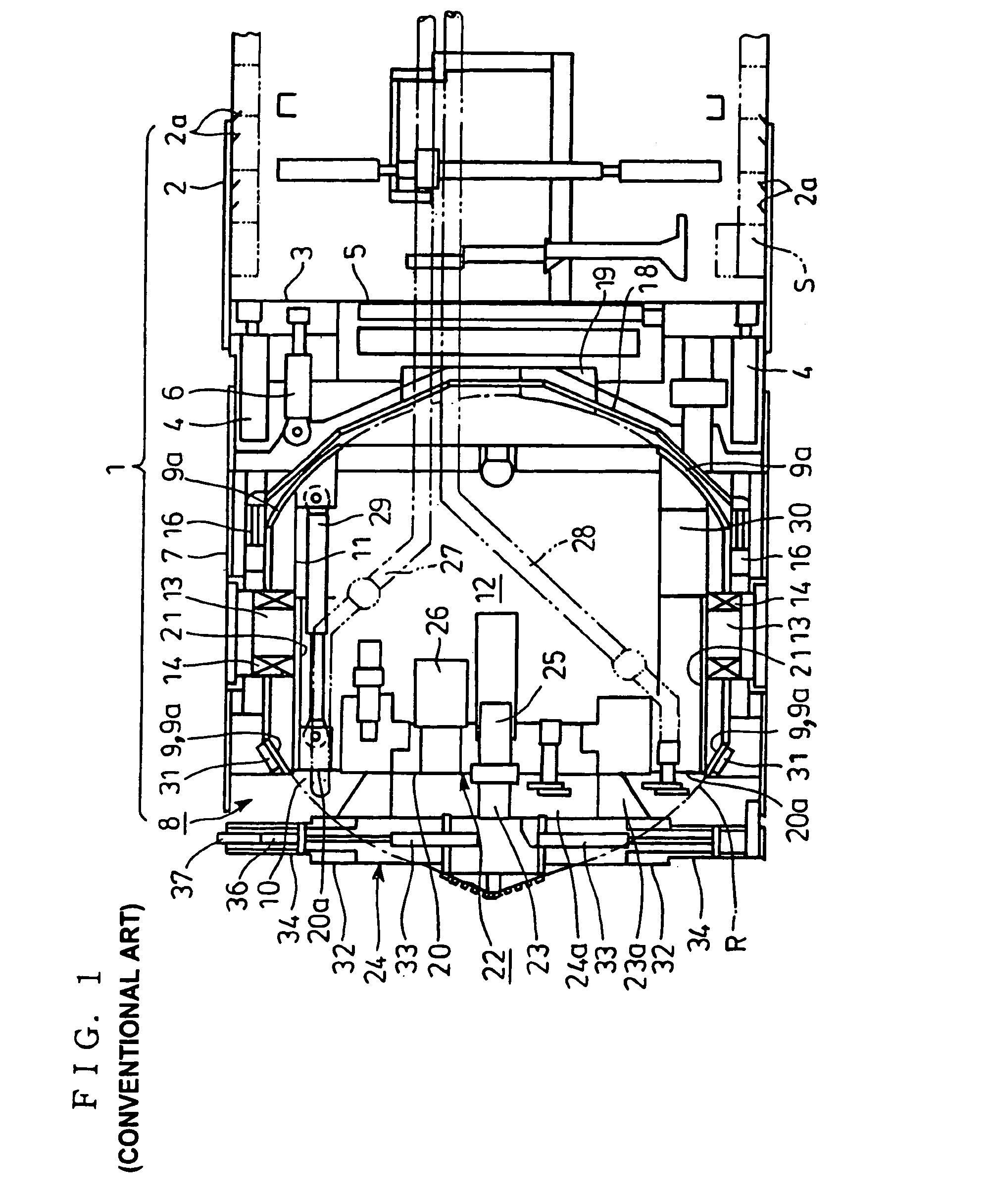
[0068]According to the first embodiment shown in FIGS. 4 and 5, a rotary shield device 8 has an excavating drive 22 with a cutter device 38 structurally different from the conventional cutter device 24 shown in FIGS. 1 and 2.

[0069]More specifically, disposed ahead of a rotor 20 rotate...

second embodiment

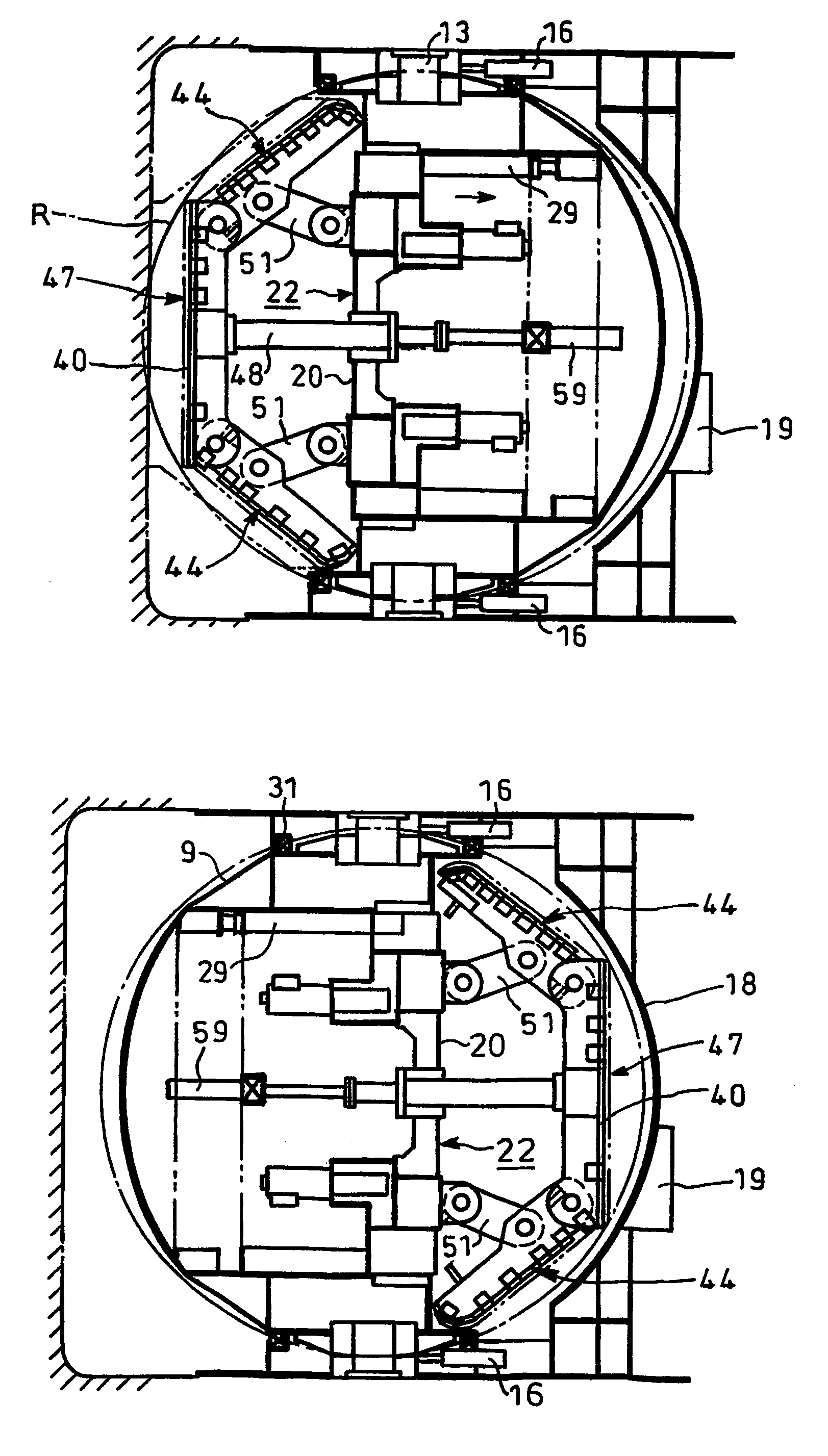
[0085]FIGS. 8 through 11 show a shield tunneling machine according to the invention.

[0086]The second embodiment has, as shown in FIGS. 8 and 9, a cutter device 47 which is ahead of an excavating drive 22 and which has a center shaft 48 movable backward / forward. The center shaft 48 has a rear end passing through the rotor 20 of the excavating drive 22 as well as a front end to which is fixed a face plate type center cutter 40 with a polygonal counter (an octagonal counter in FIG. 9). The center cutter 40 is shaped to be accommodated in the turning trajectory R of the turnable body 9 when it is retracted toward the excavating drive 22 as shown in FIG. 8. Alternatively, the center cutter 40 may have radially extending cutter frames 39 and substantially triangular face plates 41 with take-in slots 42 between the cutter frames 39 as shown in FIG. 5.

[0087]The polygonally countered center cutter 40 has outer edges having shafts 43 extending along the edges, respectively. Fitted to each of ...

third embodiment

[0110]FIGS. 16 through 22 show a shield tunneling machine according to the invention in which used in lieu of the stopper means in the form of the connectors 58 in the embodiment of FIGS. 8 through 11, is stopper means in the form of a peripheral ring 62 shaped to extend along the front end of the skin plate 7. Alternatively, such stopper means in the form of the peripheral ring 62 may be provided in addition to the stopper means in the form of the connectors 58 as shown in the embodiment of FIGS. 8 through 11.

[0111]The peripheral ring 62 is annular, and extends along the front end of the skin plate 7 as shown in FIGS. 17 through 19. There is provided in the front end of the skin plate 7 horizontal thrust jacks 63 each extending in the direction of tunneling. Each of the thrust jacks 63 has a tip end with a retaining jack 64 attached thereto and extending radially and inwardly of the shield body 1. Each of the retaining jacks 64 may be expanded and contracted to be fitted into and r...


PUM


Abstract

An excavating drive (22) movable backward / forward is accommodated in a turnable body (9) which in turn is turnable about an axis perpendicular to an axis of and in a skin plate (7). A cutter device (38) ahead of a rotor (22) in the excavating drive (22) is composed of a center cutter (40) supported by the excavating drive (22) and a plurality of face plate shaped expansion cutters (44) fitted to an outer periphery of the center cutter (40) for pivotal movement backward / forward. Tunneling is effected by the expanded cutter device with the expansion cutters (44) being pivoted forward. Upon replacement of bits (35; 35′), the expansion cutters (44) are pivoted backward for contraction of an assembly of them and the cutter device (38) is accommodated in a turning trajectory (R) of the turnable body (9) so that the turnable body (9) is turned backward for replacement of the damaged bits (35; 35′) backward.

Description

TECHNICAL FIELD[0001]The present invention relates to a shield tunneling method and a shield tunneling machine, using a face plate type cutter device with bits.BACKGROUND ART[0002]Continual tunneling of a long-distance tunnel will require replacement of damaged bits on a cutter device with tunneling being halted halfway. In order to comply with such requirement, there has been proposed a shield tunneling machine with a turnable body. This turnable body, which is disposed in a skin plate and ahead of a shield frame, is turnable about an axis perpendicular to an axis of the tunneling machine and accommodates an excavating drive with a cutter device ahead thereof, so that turning of the turnable body causes the cutter device to be directed backward, which facilitates replacement of damaged bits on the cutter device backward with tunneling being halted halfway; in this respect, words such as “forward”, “backward”, “front” and “rear” in the specification are referred to in relation with ...

Claims


Application Information

Patent Timeline
Patent Type & Authority Patents(United States)
IPC IPC(8): E21B3/00E21D9/10E21D9/08E21D9/087
CPCE21D9/081E21D9/0879
Inventor SAKAE, TAKESHISONOMURA, SHUNICHINAITOU, WATARUITOU, HIROYUKINAKANE, TAKASHIMIZUNO, SHUUSUKESUGIMORI, SHIN
Owner TAISEI CORP
Features
  • R&D
  • Intellectual Property
  • Life Sciences
  • Materials
  • Tech Scout
  • Unparalleled Data Quality
  • Higher Quality Content
  • 60% Fewer Hallucinations
Learn More