Check patentability & draft patents in minutes with Patsnap Eureka AI!

Construction method for replacing valve under pressure for liquid nitrogen freezing bridge plug

A valve replacement and liquid nitrogen freezing technology, which is applied in the field of oil and gas field exploration and development, can solve problems such as affecting operations, collision of excavation equipment wellhead gates, low freezing efficiency, etc., and achieve the effects of reducing operating time, improving freezing efficiency, and reducing operating costs

Active Publication Date: 2020-11-27
BC P INC CHINA NAT PETROLEUM CORP +1
View PDF8 Cites 0 Cited by
  • Summary
  • Abstract
  • Description
  • Claims
  • Application Information

AI Technical Summary

Problems solved by technology

[0002] After years of development, the process of replacing valves with frozen bridge plugs has become mature. It is basically finalized as digging a working pit around the wellhead, installing a ring-shaped freezing box around the surface casing, adding refrigerant, pre-freezing, making frozen bridge plugs, and replacing valves. A process, on the whole, the effect is not bad, but in the process of operation, there are still many disadvantages and hidden dangers, mainly concentrated in the first two links: first "digging the working pit around the wellhead": the original process required digging around the wellhead Due to the influence of the wellhead equipment, the working square pit with a length, width and height of 2 meters is very difficult to construct on two sides. The excavation equipment is easy to collide with the wellhead gate, which poses a safety hazard
The second "install the ring-shaped freezing box around the surface casing": due to the limitation of the working pit space, the height of the ring-shaped freezing box is only 550mm, the thickness of the formed frozen bridge plug is less than 0.6 meters, and the effective volume of the frozen medium is only 0.15m 3 , the freezing efficiency is low; the ring-shaped freezing box is made of two semicircular metal boxes buckled outside the sleeve, with a rubber piece in the middle, and assembled with clamps and screw rods. Different specifications of sleeves require Processing freezer boxes of different sizes
The metal parts between the freezing box and the casing are hard-connected, and it is difficult to make it just right, so it often leaks when containing the freezing medium
The commonly used freezing medium is a mixture of dry ice and methanol, which is very slippery when it flows into the work pit. Methanol is corrosive and toxic, which affects personnel working in the work pit.
In addition, a large amount of carbon dioxide gas is easy to accumulate in the working pit, and it is easy to suffocate when adding freezing medium inside

Method used


Image

  • Construction method for replacing valve under pressure for liquid nitrogen freezing bridge plug
  • Construction method for replacing valve under pressure for liquid nitrogen freezing bridge plug

Examples


Embodiment 1

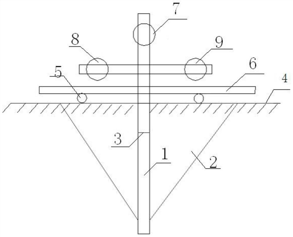
[0031] Such as Figure 1-2 As shown, a construction method for liquid nitrogen frozen bridge plug replacement valve under pressure includes the following steps:

[0032] 1) Take the casing 1 of the gas production wellhead where the valve is to be replaced as the center, and dig the liquid storage pit 2 toward the ground 4 in the circumferential direction;

[0033] 2) Mark the highest liquid level mark line 3 on the casing 1 in the liquid storage pit 2;

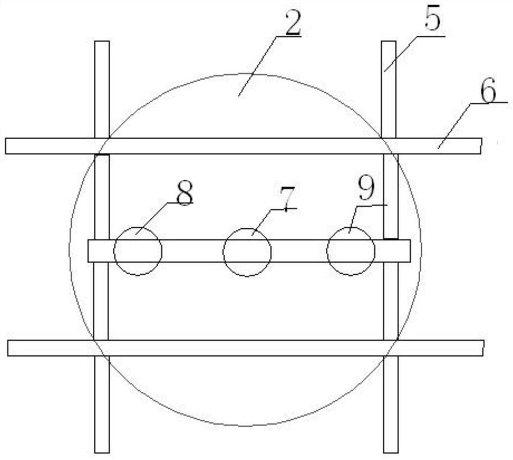
[0034] 3) Build a steel pipe skeleton on the ground 4 centering on the gas production wellhead where the valve is to be replaced;

[0035] 4) Install pedals on the steel pipe skeleton along the arrangement direction of the main control valves at the gas production wellhead;

[0036] 5) Inject liquid nitrogen into the liquid storage pit 2 until the liquid nitrogen liquid level reaches the highest liquid level mark line 3;

[0037] 6) Lay insulation pads on the pedals;

[0038] 7) making frozen bridge plugs;

[0039] 8) Rep...

Embodiment 2

[0043] On the basis of Example 1, the shape of the liquid storage pit 2 is conical with the tip pointing downward. The liquid storage pit 2 is conical, and the conical working space is used to directly contain the freezing medium, eliminating the freezing box, increasing the contact area between the freezing medium and the casing, and canceling the limited space of the working pit.

[0044] Further, the conical pit refers to a conical space with a diameter of 2.0m and a depth of 2.0m surrounding the casing 1 of the gas production wellhead, which is used to store liquid nitrogen, so that the amount of ground work is only 1 / 3 of the previous one, and the amount of freezing medium is 1 / 3. The effective volume is 4.26 times that of the previous one, and the freezing efficiency is high.

Embodiment 3

[0046] On the basis of Example 2, the distance between the highest liquid level marking line 3 and the ground 4 is ≥0.5m. Prevent the liquid nitrogen level from being too high to freeze the wellhead sealant and cause the wellhead seal to fail. The highest liquid level mark line is marked with red pigment, and the red mark is more eye-catching and easy to identify.

[0047] Further, after marking the highest liquid level mark line 3 in the step 2), it is necessary to spray liquid nitrogen on the conical slope in the liquid storage pit 2 . Use the liquid nitrogen output pipeline to evenly spray liquid nitrogen once on the conical slope 2, so that the slope is hardened and does not leak, and at the same time, solid phases such as soil clods do not fall, thereby improving construction safety.

[0048] Further, after the liquid nitrogen is sprayed on the tapered slope, liquid nitrogen needs to be uniformly sprayed around the casing 1 . Spray evenly around the casing 1 with liquid...


PUM


Abstract

The invention belongs to the technical field of exploration and development of oil-gas fields, and specifically provides a construction method for replacing a valve under pressure for a liquid nitrogen freezing bridge plug. The construction method comprises the following steps: digging a liquid storage pit in ground in the peripheral direction by taking a sleeve with a valve to be replaced as a center; marking a highest liquid level marker line on the sleeve in the liquid storage pit; establishing a steel tube framework on ground by taking a gas recovery well mouth of the valve to be replacedas the center; mounting a pedal on the steel tube framework; injecting liquid nitrogen into the liquid storage pit until the liquid level reaches the highest liquid level marker line; paving a thermalinsulation pad on the pedal; manufacturing a freezing bridge plug; replacing an invalid valve; sequentially dismounting the thermal insulation cushion, the pedal and the steel tube framework, openingthe liquid storage pit to volatilize liquid nitrogen therein, and backfilling earth into the liquid storage pit with liquid nitrogen completely volatized to accomplish the construction. The construction method solves the problems that a conventional freezing valve-replacing process is great in construction difficulty, is high in potential safety hazard, is low in freezing efficiency and the like,and has the characteristics of improving freezing efficiency, reducing operation time, and reducing operation cost.

Description

technical field [0001] The invention belongs to the technical field of oil and gas field exploration and development, and in particular relates to a construction method for replacing valves under pressure with liquid nitrogen frozen bridge plugs. Background technique [0002] After years of development, the process of replacing valves with frozen bridge plugs has become mature. It is basically finalized as digging a working pit around the wellhead, installing a ring-shaped freezing box around the surface casing, adding refrigerant, pre-freezing, making frozen bridge plugs, and replacing valves. A process, on the whole, the effect is not bad, but in the process of operation, there are still many disadvantages and hidden dangers, mainly concentrated in the first two links: first "digging the working pit around the wellhead": the original process requires digging around the wellhead Due to the impact of the wellhead equipment, the working square pit with a length, width and hei...

Claims


Application Information

Patent Timeline
Patent Type & Authority Applications(China)
IPC IPC(8): E21B23/00E21B33/134
CPCE21B23/00E21B33/134
Inventor 畅毅刘建芝陈磊温亚魁刘洋雷璠王巍岚王旭赵志华薛景仰
Owner BC P INC CHINA NAT PETROLEUM CORP
Features
  • R&D
  • Intellectual Property
  • Life Sciences
  • Materials
  • Tech Scout
  • Unparalleled Data Quality
  • Higher Quality Content
  • 60% Fewer Hallucinations
Learn More