Contact lens and methods of manufacture and fitting such lenses and computer program product

a technology of contact lenses and computer programs, applied in the field of contact lenses and methods of manufacture, can solve the problems of increasing the cost of general use of such procedures, increasing the cost of such procedures, and affecting so as to improve the ability of fitters, facilitate design or correction, and facilitate the effect of formation

Inactive Publication Date: 2006-05-09
PARAGON CRT CO LLC +2
View PDF30 Cites 32 Cited by
  • Summary
  • Abstract
  • Description
  • Claims
  • Application Information

AI Technical Summary

Benefits of technology

[0006]In accordance with the foregoing, it is an object of the present invention to provide a CRT contact lens, method of manufacturing such lenses and methods of designing and fitting lenses and a software product for design of such a lens. The contact lens according to the invention overcomes the deficiencies of the prior art, and provides a design which allows proper fitting of a patient, whether for corrective contact lenses or for use in an orthokeratology treatment program. The ability to properly fit a patient will alleviate, at least to a great degree, corneal abrasions from poorly distributed bearing, corneal warpage from decentered lenses, edema from tight fitting lenses and discomfort from excessive lens edge standoff. The simplified design allows a novice or relatively unskilled fitter to visualize the relationship between the contact lens and cornea of a patient's eye. The design and corresponding relationship to the patient's cornea allows selection of original trial lenses and any subsequent modifications to be easily designed or corrected. The lens design also provides improved ability of a fitter to consult with a lens designer to discuss clearly the lens cornea relationship for determining of the lens design. Due to the rational design of the lenses according to the present invention, a minimal number of lens parameter increments can be identified to cover the range of common corneas. It is therefore possible to provide pre-formed lens buttons or blanks which are easily formed into a final design, thereby simplifying and speeding up the treatment process. Further, any adjustment of the lens design which may be required based upon trial fitting or the like, is easily envisioned and communicated by the fitter and fabricated by the manufacturer.
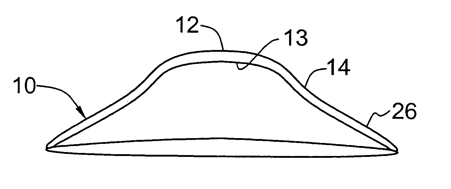
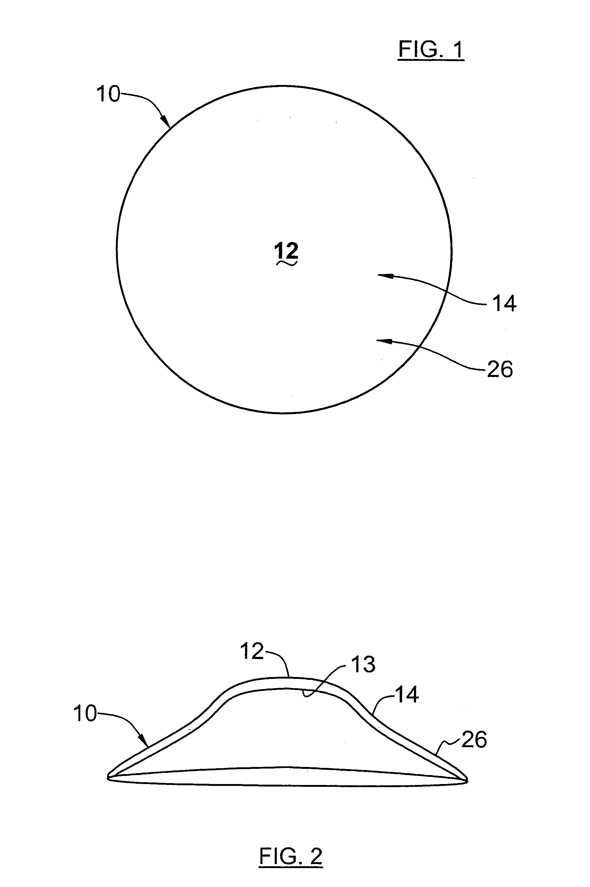
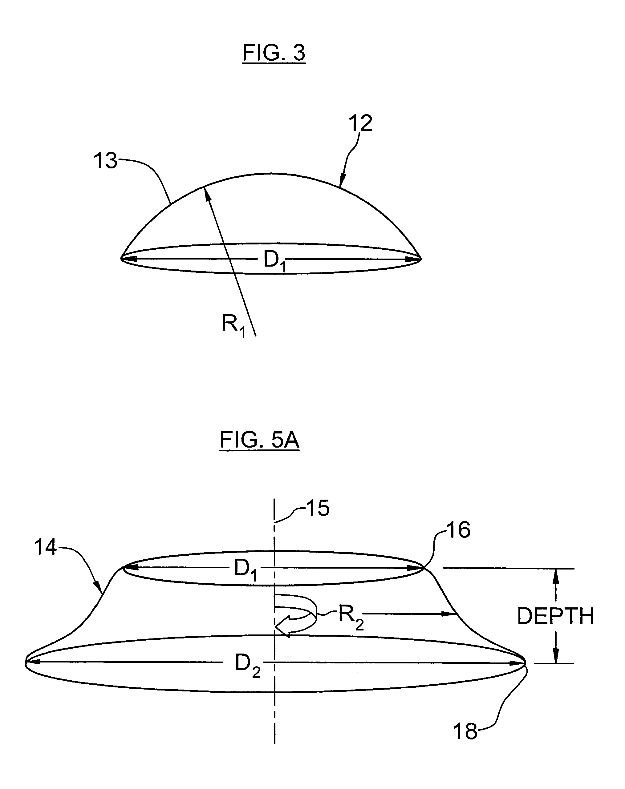
[0007]In accordance with this and other objects of the invention, there is provided a contact lens comprising 1) a central zone having a posterior surface having a curvature determined by the correction or reshaping to be imparted to the cornea; 2) a connecting zone is provided adjacent and concentric to the central zone, the connecting zone having a shape defined by a first generally posteriorly concave portion adjacent the central zone (this concave portion being initially of longer radius than the central zone then becoming steeper than the central zone until nearly parallel to the central axis of the lens) and transitioning to a generally posteriorly convex portion thus having the appearance of an elongated backward “S” or sigmoidal shaped curve; and 3) a peripheral zone is provided adjacent and concentric to the connecting zone, and is provided with a conoid shape. In a CRT lens, the peripheral zone is used to facilitate redistribution of the corneal tissue with the central zone by maintaining centration during treatment. The design of peripheral zone also minimizes the potential for its extreme edge or its junction with the first annular zone to impinge directly on the cornea, even after ultimate contact.

Problems solved by technology

Although the use of contact lenses is widespread, there are potential difficulties in properly fitting a lens for a patient, which in turn could damage the patient's cornea or cause discomfort.
The popularity of such techniques has increased greatly, but still carry risk in both the procedure itself as well as post surgical complications.
It is also typical of orthokeratology treatment plans that the lenses used for reshaping of the cornea must be custom designed and manufactured, thereby greatly increasing the cost and complicating general use of such procedures.
Further, orthokeratology lenses typically have various deficiencies, particularly relating to properly designing a lens for a particular patient to achieve best results in the treatment process.
Specifically corneal abrasions from poorly distributed bearing, corneal warpage from decentered lenses, edema from tight fitting lenses and discomfort from excessive lens edge standoff are problems associated with an improperly fit lens.
The design of orthokeratology lenses have not lent themselves to be easily fitted for a particular patient and their needs, requiring a doctor or other practitioner to have significant skill in complex geometric computation to properly mate the lens shape to the patients cornea and a high level of expertise in properly fitting a patient.
Further, even with a high level of expertise, a lens designer many times will design a lens which will not work properly with a patient, and must be redesigned to account for the errors of the original design.
Such a process is lengthy and increases the cost of the treatment correspondingly.
Another deficiency of ortho-K lenses is found in the complexity of the designs, which exacerbate the fitting problems mentioned previously.
In the fitting process, if there is an aspect of the lens design which is not properly fitted for the desired treatment of the patients eye, or causes excessive discomfort to the patient, the lens must be redesigned accordingly.
Unfortunately, in an attempt to redesign a lens, a practitioner may affect other aspects of the lens due to the interdependency between design features or may not anticipate manufacturing variances required by the altered design.

Method used


Image

  • Contact lens and methods of manufacture and fitting such lenses and computer program product
  • Contact lens and methods of manufacture and fitting such lenses and computer program product
  • Contact lens and methods of manufacture and fitting such lenses and computer program product

Examples


example 1

[0065]This example is based upon a patient having a prescription as follows:

1. 44.50×46.00@180, Rx−4.00−0.75×180, e=0.5, HVID 11.6

Based upon the prescription of patient 1 above, a lens designer would select the power of the lens to correct the patient to a desired degree. In this example, with reference to FIG. 9, the lens / cornea power difference wanted for patient 1 is selected as −4.5 diopters as indicated at 200. The power difference selected is slightly more than the degree of correction required for the patient, to allow substantial correction of visual acuity over a longer period of time after reshaping of the cornea using the lens according to the invention. Patient 1 also has a fairly high astigmatism of 0.75, and the ellipticity of the cornea is 0.5 as shown at 202. Patient 1 has an HVID of 11.6, as noted at 204, and based upon this HVID, the diameter of the lens which is recommended is 10.6 mm as indicated at 206, being 1 mm less than the measured HVID. The selected diamet...

example 2

[0066]For patient 2, having a prescription as follows:

42.00×44.00@165, Rx−3.50−1.00×160, e=0.6, HVID 11.4

With patient 2, a relatively high refractive error along with high astigmatism is noted, which again will lead the lens designer to increase the value of the ellipticity of the cornea as shown at 230 in FIG. 14. Due to the high astigmatism, it is desired to have a thicker center in the lens, which again is easily accommodated by varying the delta r for the first junction between the base curve and the sigmoidal curve as shown at 232. Other aspects of the particular lens design for patient 2 are determined in a manner similar to that described with reference to patient 1 in Example 1. Particular values for the variables, including base curve, lens diameter, angle of the peripheral zone as well as depth of the sigmoidal curve are shown in FIG. 14, with the relationship between the zones shown graphically in FIG. 15. The relatively thick center and thinner edge portion in this lens ...

example 3

[0067]For patient 3 having a prescription as follows:

46.50×46.50@180, Rx−6.00−0.75×90, e=0.4, HVID 11.2

With reference to FIGS. 19–23, a lens design according to the present invention for patient 3 is shown. Selecting parameters of the base curve, base diameter, angle of peripheral zone as well as depth of the sigmoidal curve are selected in a manner similar to that previously described, providing a first indication of fit to the lens designer. For patient 3 using a value of 3.0 mm as the radial distance from the lens center to the first junction, which may in general be held uniform, produced a relatively large void space adjacent the base curve at the first junction. The lens designer therefore has the flexibility to reduce or narrow the optical zone, as indicated by the use of 2.5 mm at 210 and increases the width of the sigmoidal curve indicated at 212 as 2.0. The relationship of the zones relative to one another and the cornea are shown in FIGS. 20–23, wherein the void space adj...


PUM


Abstract

The invention is directed to a contact lens design and methods of manufacturing, fitting and using such lenses. The contact lens may be designed for use in a corneal refractive therapy (CRT) program. The lens provides a design which allows proper fitting of a patient, whether for corrective contact lenses or for a CRT program. Due to the rational design of the lenses according to the present invention, a minimal number of lens parameter increments can be identified to cover the range of common corneas. It is therefore possible to provide pre-formed lens buttons or blanks which are easily formed into a final design, thereby simplifying and speeding up the treatment process. Further, any adjustment of the lens design which may be required based upon trial fitting or the like, is easily envisioned and implemented by the fitter.

Description

[0001]This application claims the benefit of U.S. Provisional Application No. 60 / 214,554 filed Jun. 27, 2000.TECHNICAL FIELD[0002]This invention relates to contact lenses and methods of manufacture, as well as methods for reshaping the cornea of an eye to treat visual acuity deficiencies. The invention is more particularly related to non-surgical methods of reshaping the cornea. This procedure maybe referred to as Corneal Refractive Therapy (CRT) when the therapy relates to designing and fitting a single contact lens to reshape the cornea, and / or orthokeratology (ortho K) when referring to the use of a series of lenses for the purpose of reshaping the cornea. The invention further relates to methods of fitting contact lenses and designing such lenses, as well as a software product for designing such lenses.BACKGROUND OF THE INVENTION[0003]In the treatment of visual acuity deficiencies, correction by means of eyeglasses or contact lenses are used by a large percentage of the populati...

Claims


Application Information

Patent Timeline
Patent Type & Authority Patents(United States)
IPC IPC(8): G02C7/04G06F9/00G06F17/50
CPCG02C7/047
Inventor LEGERTON, JEROME A.MEYERS, WILLIAM E.
Owner PARAGON CRT CO LLC
Why Eureka
Try Eureka