Detent escapement for a timepiece

Active Publication Date: 2006-05-09
MONTRES BREGUET
View PDF10 Cites 8 Cited by
  • Summary
  • Abstract
  • Description
  • Claims
  • Application Information

AI Technical Summary

Problems solved by technology

The foregoing identifies a weakness affecting the detent escapement, namely that it is very sensitive to shocks, thus this escapement is reserved especially for chronometers of large dimensions or marine chronometers that are not mechanically stressed, said escapement having the reputation of not being suited to wristwatches.

Method used


Image

  • Detent escapement for a timepiece
  • Detent escapement for a timepiece
  • Detent escapement for a timepiece

Examples


Embodiment Construction

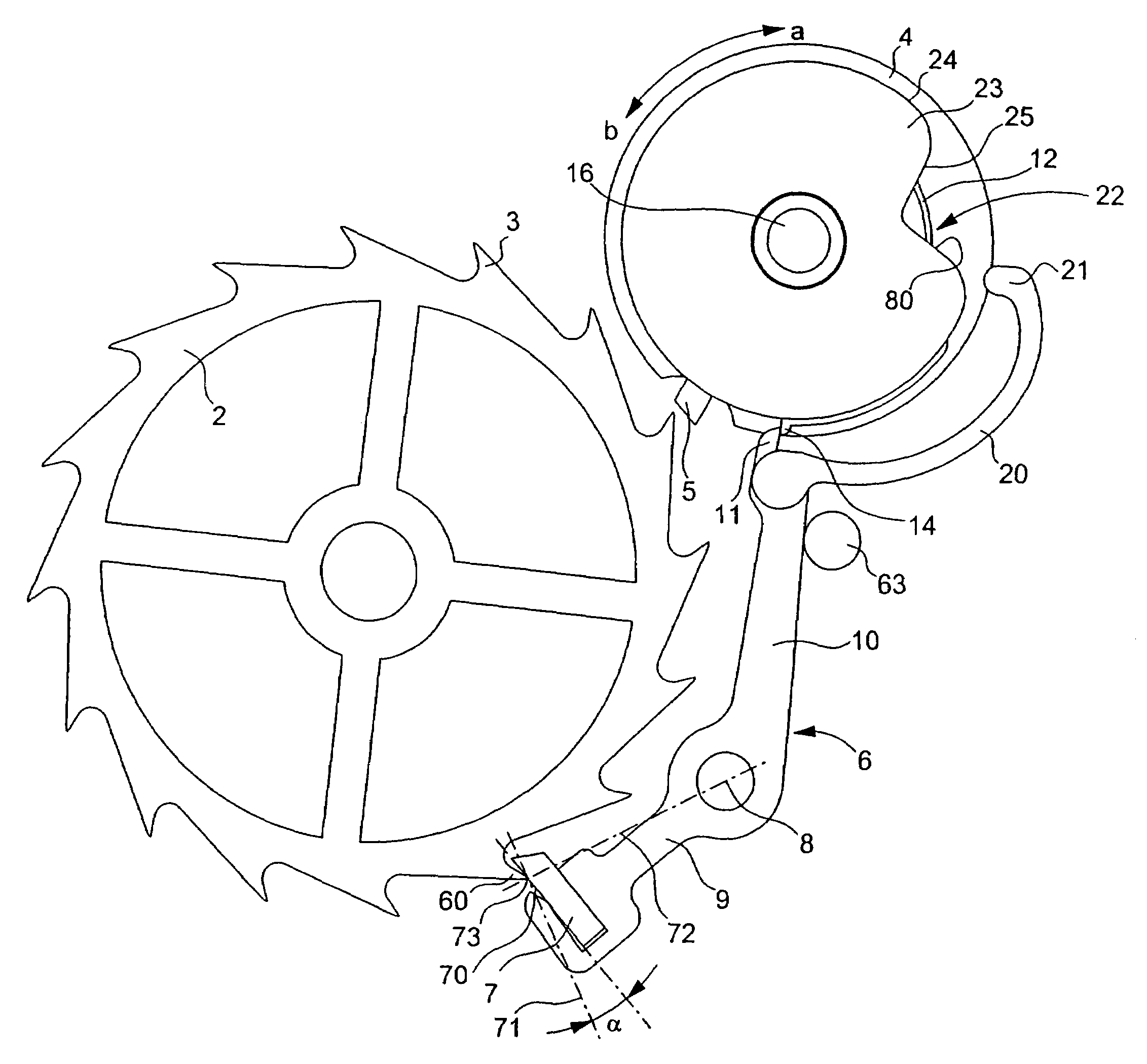
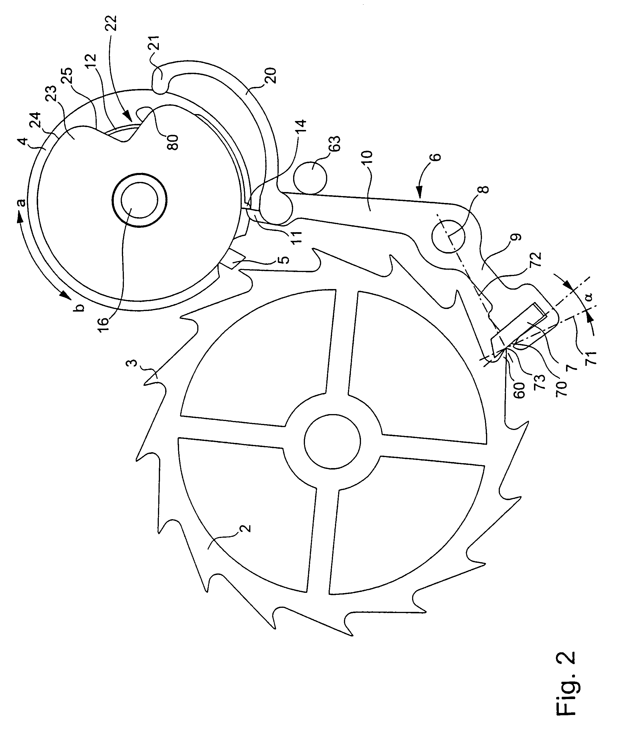
[0017]FIGS. 2, 3 and 4 illustrate the detent escapement that forms the subject of the present invention. The escapement includes an escapement wheel 2 fitted with teeth 3. Although not shown in the drawings, the escapement wheel is driven by the gear train of the timepiece, which receives its driving force from a barrel. The Figures show a large roller 4 mounted on the pin or arbour 16 of the balance (not shown). The large roller 4 is fitted with a first actuating finger 14 and an impulse pallet stone 5 receiving pulses from teeth 3 of wheel 2. The system also shows a blocking member in the form of a lever 6 hinged on a pin 8. The blocking member 6 carries a locking pallet-stone 7, a second actuating finger 11 and a follower 20 terminated by beak 21. The locking pallet-stone cooperates with teeth 3 of wheel 2. The escapement further includes an elastic member acting on one of the actuating fingers—in the case of FIGS. 2 to 4 on finger 14—to drive the other finger—finger 11 in this c...


PUM


Abstract

The blocking member (6) or detent member of the escapement carries a follower (20) which ends in a beak (21) which cooperates with a small roller (23) comprising a notch (22). When the locking pallet-stone (7) of the blocking member releases itself from the teeth of escapement wheel (2), the beak (21) penetrates in the notch (22). The return of the pallet-stone (7) in the locking position is caused by a rising flank (25) of said notch, said rising flank being inclined such that the beak (21) is forced to follow and climb over said flank when the small roller (23) rotates. The arrangement allows the escapement to resist to shocks and consequently to omit the return spring acting on the blocking member.

Description

[0001]This application claims priority from European Patent Application 03027929.3 filed Dec. 4, 2003, the entire disclosure of which is incorporated herein by reference.FIELD OF THE INVENTION[0002]The present invention relates to a detent escapement for a timepiece including an escapement wheel, a balance on the pin of which are fixed a large roller fitted with an impulse pallet-stone and a first actuating finger, a blocking member in the form of a lever hinged on a pin, said blocking member carrying a locking pallet stone, a second actuating finger and a follower which ends in a beak, said escapement further including an elastic member acting on one of the actuating finger to drive the other finger and actuate the blocking member when the roller rotates in a first direction and to move around said other finger without driving the roller when said roller rotates in a second direction opposite to the first, the pin of the balance further carrying a small roller in the circular perip...

Claims


Application Information

Patent Timeline
Patent Type & Authority Patents(United States)
IPC IPC(8): G04B15/00G04B15/06G04B15/14
CPCG04B15/06
Inventor HAYEK, NICOLAS GEORGESCONUS, THIERRYCABEZAS JURIN, ANDRES
Owner MONTRES BREGUET
Why Eureka
Try Eureka