Electric connecting terminal
a technology of electric connecting terminals and connecting terminals, which is applied in the direction of fixed connections, contact members penetrating/cutting insulation/cable strands, printed circuit manufacturing, etc., can solve the problems of mechanical connection strength reduction and deterioration of conductance reliability, and achieve the effect of enhancing conducting reliability for a flat circuit body
- Summary
- Abstract
- Description
- Claims
- Application Information
AI Technical Summary
Benefits of technology
Problems solved by technology
Method used
Image
Examples
first embodiment
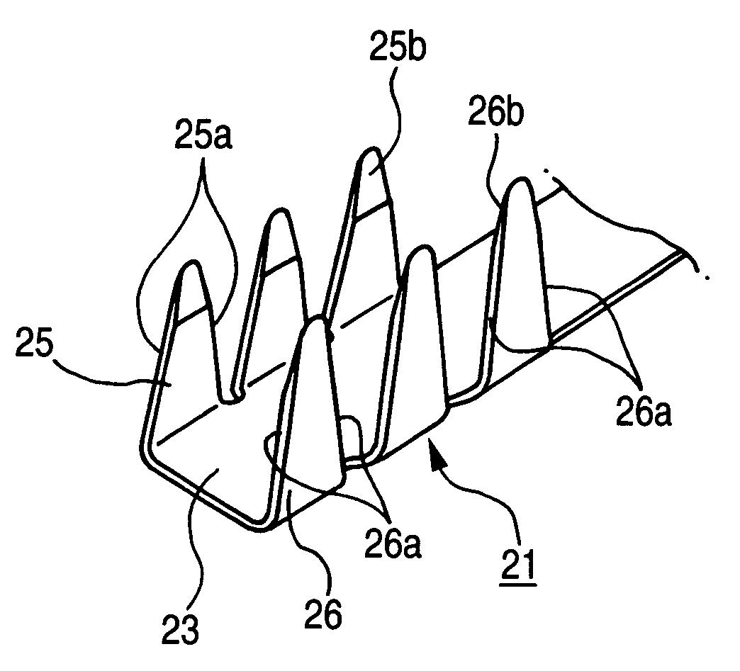
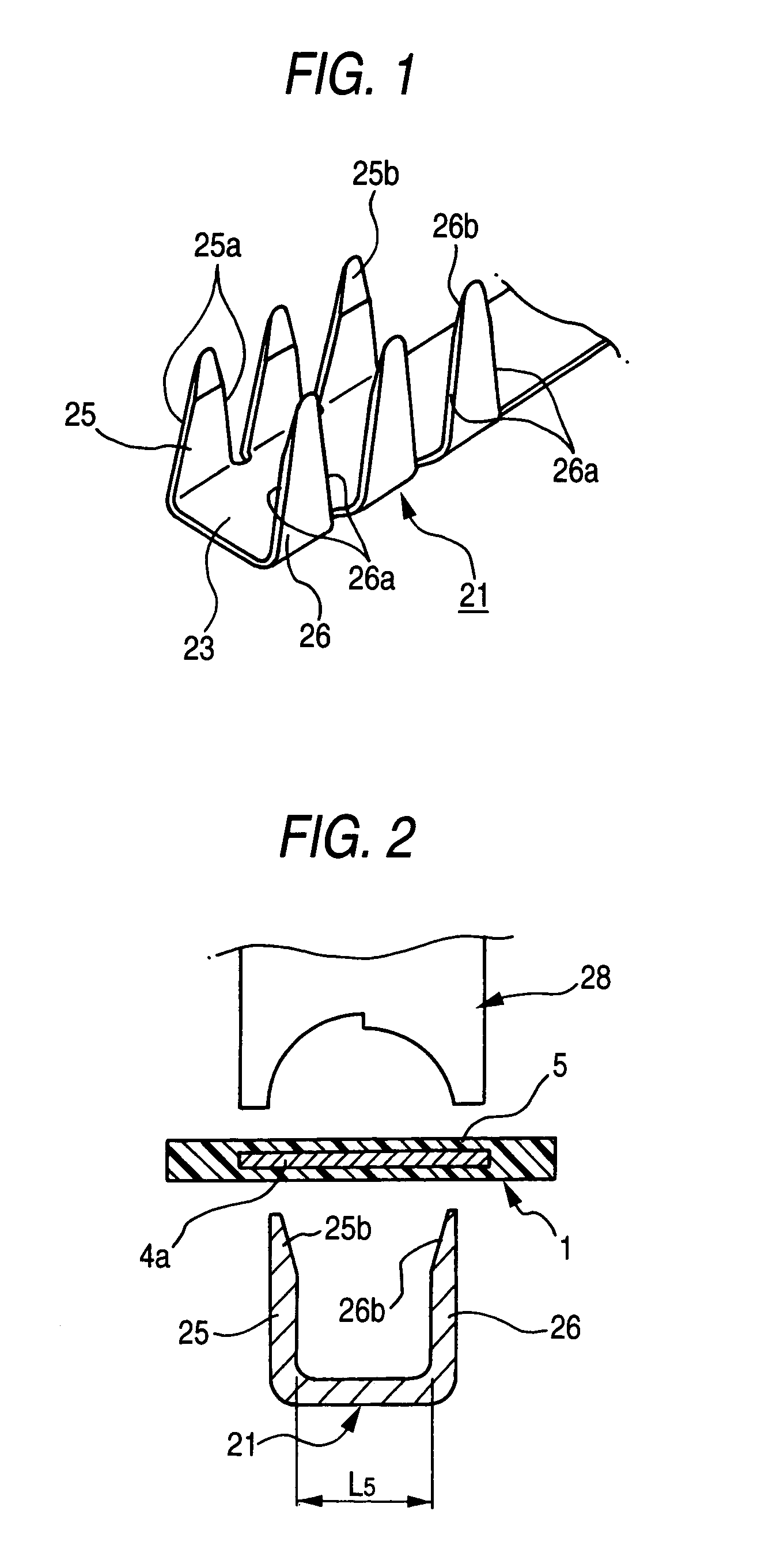
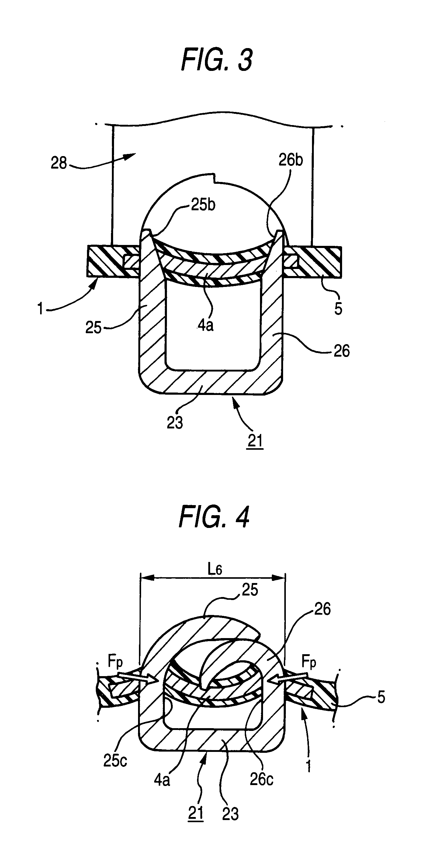
[0066]FIG. 1 is a perspective view showing a main part of an electric connecting terminal according to the invention, FIGS. 2 and 3 are cross-sectional views illustrating a procedure for connecting the electric connecting terminal shown in FIG. 1 to a flat circuit body, FIG. 4 is a cross-sectional view showing a state in which the electric connecting terminal illustrated in FIG. 1 is connected to the flat circuit body, and FIG. 5 is an enlarged sectional view illustrating a main part of a procedure for connecting the electric connecting terminal shown in FIG. 3 to the flat circuit body.
[0067]A flat circuit body 1 for connecting an electric connecting terminal 21 according to the first embodiment has the same structure as that of the flat circuit body 1 shown in FIG. 14 and is an FFC (flexible flat cable) which is finished to be a band-shaped cable having a flexibility as a whole by coating a plurality of elongated thin-plate shaped conductors 4a, 4b, . . . with a thin film-shaped in...
second embodiment
[0081]FIGS. 6 to 8 show an electric connecting terminal 31 according to the invention.
[0082]The electric connecting terminal 31 according to the second embodiment has such a structure that taper surfaces 25d and 26d for gradually reducing plate thicknesses toward tips are added to the external surface sides of the piercing portions 25 and 26 of the electric connecting terminal 21 according to the first embodiment. Common components to those of the electric connecting terminal 21 according to the first embodiment have the same reference numerals and detailed description will be omitted.
[0083]As shown in FIGS. 6 and 7, the taper surfaces 25d and 26d are provided symmetrically in the direction of the plate thickness with respect to taper surfaces 25b and 26b formed on the internal surface sides of the piercing portions 25 and 26.
[0084]In the electric connecting terminal 31, a contact pressure between base internal surfaces 25c and 26c of the piercing portions 25 and 26 and the shear pl...
third embodiment
[0086]FIGS. 9 and 10 show an electric connecting terminal 41 according to the invention.
[0087]As shown in FIGS. 9 and 10, the electric connecting terminal 41 according to the third embodiment is connected to a flat circuit body 1 by causing the tips of three pairs of piercing portions 43 and 44 erected on both side edges of a plane portion 23 to penetrate through a coating 5 and a conductor 4a in the flat circuit body 1 and then folding the tips in such a direction as to approach each other.
[0088]The piercing portions 43 and 44 have such rectangular shapes that widths on the base portion side penetrating through the conductor 4a are almost constant, and only the tip side, which is folded after penetrating through the flat circuit body 1, is provided with taper portions 43a and 44a for gradually reducing widths and almost triangular shapes seen from the side.
[0089]Moreover, taper surfaces 43b, 43d (44b, 44d) for gradually reducing plate thicknesses toward the tips are provided on the...
PUM
 Abstract
Description
Claims
Application Information
 - R&D
- Intellectual Property
- Life Sciences
- Materials
- Tech Scout
- Unparalleled Data Quality
- Higher Quality Content
- 60% Fewer Hallucinations
Browse by: Latest US Patents, China's latest patents, Technical Efficacy Thesaurus, Application Domain, Technology Topic, Popular Technical Reports.
© 2025 PatSnap. All rights reserved.Legal|Privacy policy|Modern Slavery Act Transparency Statement|Sitemap|About US| Contact US: help@patsnap.com


