
Method for connecting electronic part and joined structure

a technology of joining structure and electronic part, which is applied in the direction of coupling device connection, paper/cardboard container, bandage, etc., can solve the problems of short circuit between the terminals, reduced properties of the conductive particles themselves, and conduction failure, etc., to achieve accurate counting, low conductive resistance, and high conduction reliability

Active Publication Date: 2012-09-25
DEXERIALS CORP
View PDF13 Cites 3 Cited by
  • Summary
  • Abstract
  • Description
  • Claims
  • Application Information

AI Technical Summary

Benefits of technology

[0019]The present invention aims at providing a method for connecting an electronic part which is capable of accurately measuring the number of captured conductive particles, and has high conduction reliability after the connection, and providing a joined structure.
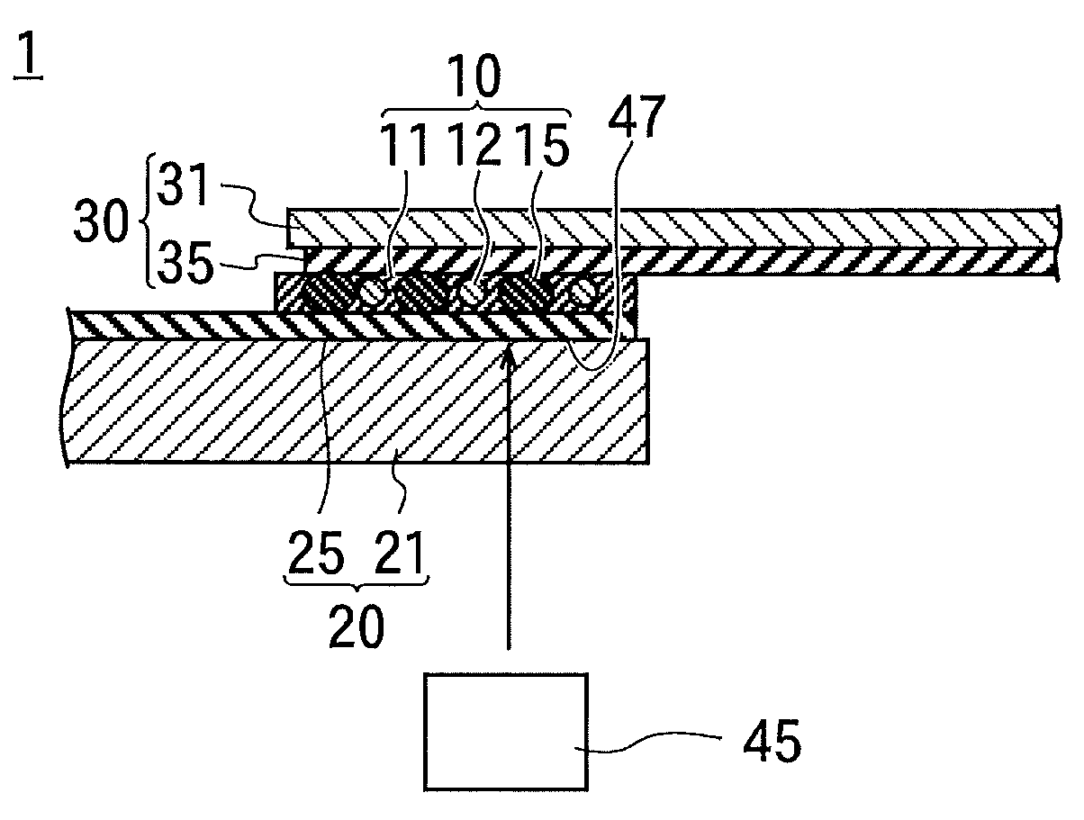
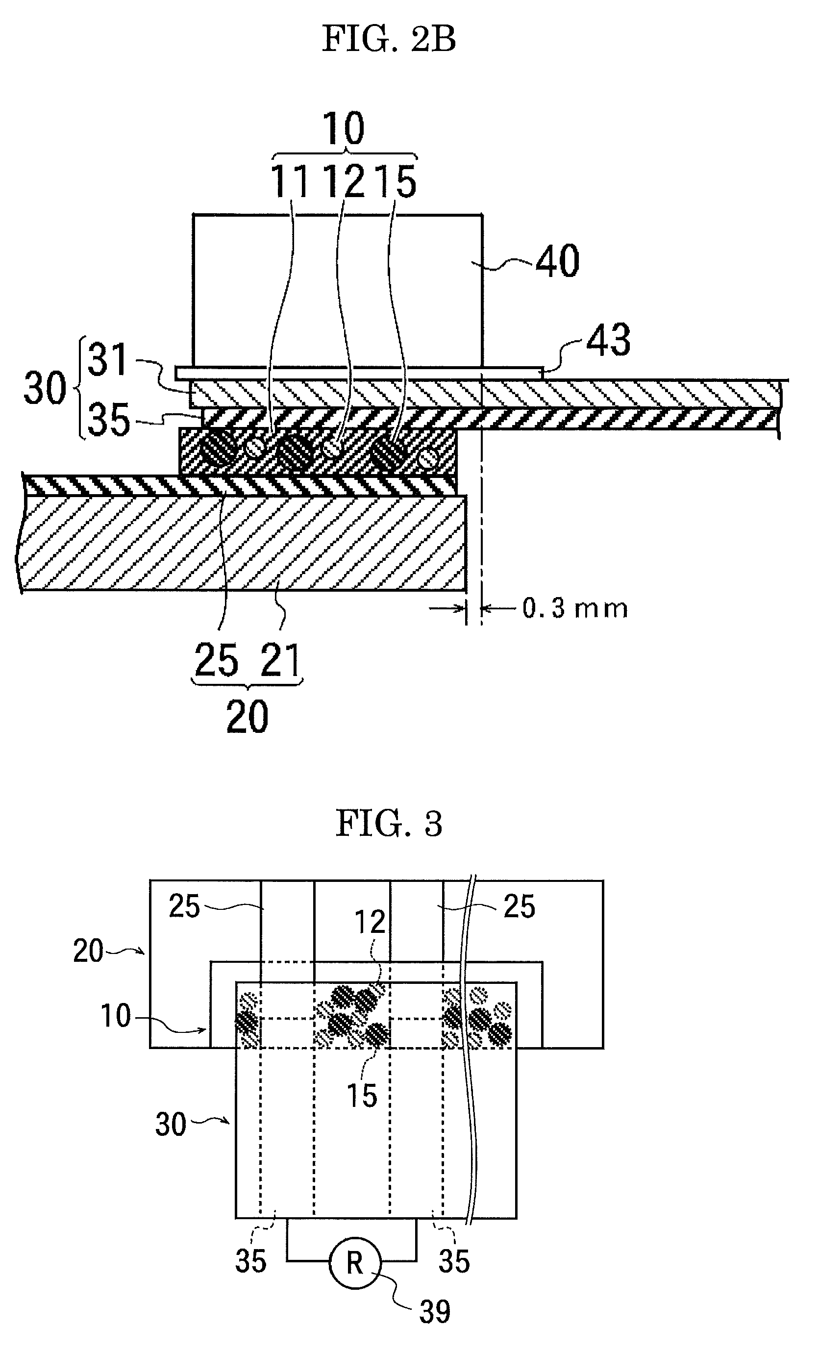
[0022]placing a terminal of a substrate and a terminal of an electronic part so as to face each other via the anisotropic conductive adhesive, and applying heat and pressure to the substrate and the electronic part so as to sandwich the conductive particles between the terminal of the substrate and the terminal of the electronic part to thereby deform the conductive particles,
[0030]According to the present invention, the conventional problems in the art can be solved, and the following objects can be achieved. Namely, the present invention can provide a method for connecting an electronic part which is capable of accurately measuring the number of captured conductive particles, and has high conduction reliability after the connection, and provide a joined structure.
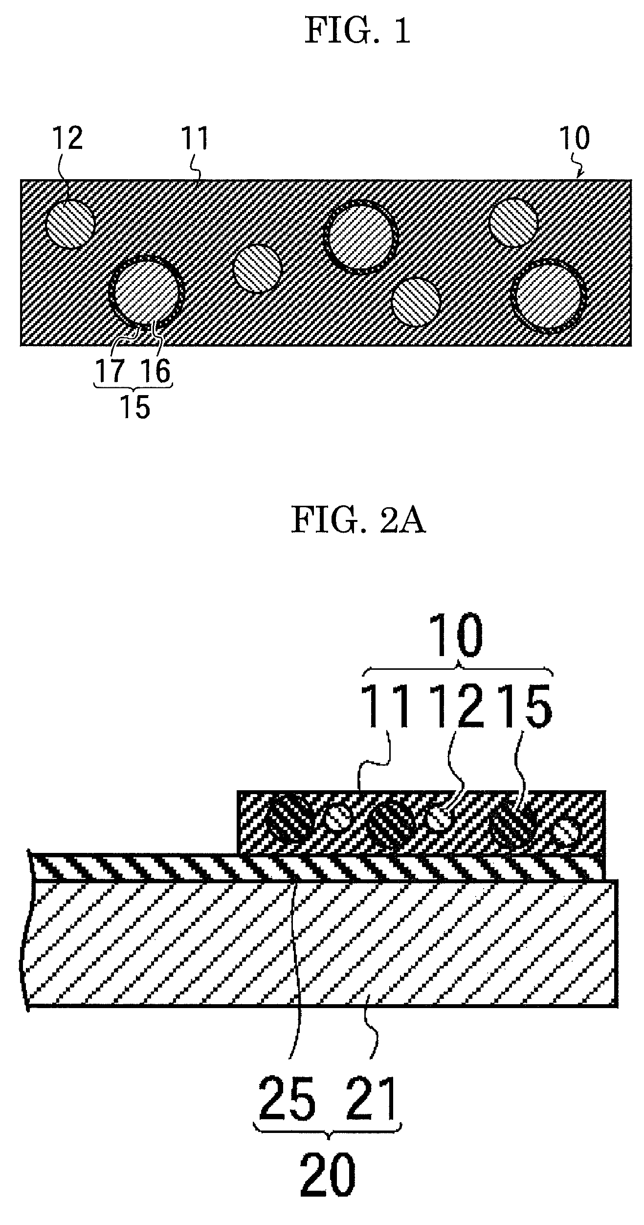
[0036]Moreover, if the particle diameters of the insulating particles are obtained in advance, it becomes clear which particle diameters are larger between the insulating particles and the destroyed particles. Therefore, it becomes clear that which pressure can be set as an upper limit of the pressure between the destroying pressure at which the conductive particles are destroyed, or the deforming pressure mentioned later, so as to deform the conductive particles in the range to have larger particle diameters than those of the insulating particles without destroying the conductive particles and to accurately measure the number of the captured conductive particles, the destroying pressure at which the conductive particles are destroyed, or the deforming pressure mentioned later.
[0038]According to the present invention, the insulating particles are not swollen, and thus does not become larger than the conductive particles. Moreover, even when the conductive particles are pressed, the pressed conductive particles do not become smaller than the insulating particles. Therefore, the particle diameters of the conductive particles do not become smaller than those of the insulating particles, and the insulating particles do not disturb the connection of the conductive particles. As a result, the conductive resistance is low. Furthermore, as only the part of the terminal of the substrate where the conductive particles are sandwiched forms a minute uplift, the number of the captured conductive particles can be accurately counted. In addition, as the conductive particles are not destroyed, high conduction reliability is attained. As the insulating particles do not absorb the dispersing solvent, no void is formed when the anisotropic conductive adhesive is heated.

Problems solved by technology

However, as pitches between terminals of an electronic part have been narrowed in recent years, there are cases where the conductive particles are aggregated between the terminals adjacent each other, causing a short circuit between the terminals.
The particles applied with the insulating coating have a problem such that a short circuit is caused with the external force enough to destroy the insulating coating at the time when the aggregation is caused.
Moreover, the occurrence of the short circuit due to the particle aggregation cannot completely prevented just by reducing the particle diameter of the conductive particles, and it is also not desirable as the properties (recovery ability and the like) of the conductive particles themselves are reduced.
Furthermore, the proposed method for reducing the particle density to thereby prevent the particle aggregation has a problem such that the capturing of particles between the terminals becomes insufficient, causing a conduction failure.
Therefore, a conduction failure may be occurred between the terminals.
Here, the minute uplifts formed by sandwiching the insulating particles between the terminal and the minute uplifts formed by sandwiching the conductive particles cannot be distinguished, and thus the number of the captured conductive particles cannot be measured accurately.
Therefore, this problem is especially serious.
Therefore, the problems such as a conduction familiar between the terminals, and measurement of the capturing number become more serious.

Method used


Image

  • Method for connecting electronic part and joined structure
  • Method for connecting electronic part and joined structure
  • Method for connecting electronic part and joined structure

Examples


Embodiment Construction

(Method for Connecting Electronic Part)

[0044]The method for connecting an electronic part of the present invention contains at least a mixing step and a heat-pressurizing step, and may further contain other steps as necessity.

[0045]The mixing step is mixing a dispersing solvent, an adhesive resin which is dissolved in the dispersion solvent, conductive particles, insulating particles each of which has a smaller particle diameter than that of the conductive particles, and arbitrarily selected other components as necessity, so as to prepare an anisotropic conductive adhesive.

-Dispersing Solvent-

[0046]The dispersing solvent is suitably selected depending on the intended purpose without any restriction. The dispersing solvent is not limited to a mixed solvent of ethyl acetate and toluene, but organic solvents such as methylethylketone (MEK), toluene, propyleneglycol monomethylether acetate (PGMAC), and ethyl acetate may be used. These organic solvents do not dissolve the organic-inorgan...


PUM

PropertyMeasurementUnit
particle diameteraaaaaaaaaa
thicknessaaaaaaaaaa
temperatureaaaaaaaaaa

Abstract

A method for connecting an electronic part, which contains: mixing a dispersing solvent, an adhesive resin which is dissolved in the dispersing solvent, conductive particles, and insulating particles which have smaller particle diameters than those of the conductive particles so as to prepare an anisotropic conductive adhesive; placing a terminal of a substrate and a terminal of an electronic part so as to face each other via the anisotropic conductive adhesive, and applying heat and pressure to the substrate and the electronic part so as to sandwich the conductive particles between the terminal of the substrate and the terminal of the electronic part to thereby deform the conductive particles, in which the pressure is smaller than pressure at which the conductive particles are destroyed, and smaller than pressure at which the particle diameters of the conductive particles become equal to the particle diameters of the insulating particles.

Description

CROSS-REFERENCE TO RELATED APPLICATION[0001]This is a continuation of Application No. PCT / JP2008 / 059388, filed on May 21, 2008.BACKGROUND OF THE INVENTION[0002]1. Field of the Invention[0003]The present invention relates to a method for connecting an electronic part, especially to a method for connecting an electronic part using an anisotropic conductive adhesive, and to a joined structure.[0004]2. Description of the Related Art[0005]An anisotropic conductive adhesive, in which conductive particles are dispersed in an adhesive, has been conventionally used for a connection of an electronic part.[0006]However, as pitches between terminals of an electronic part have been narrowed in recent years, there are cases where the conductive particles are aggregated between the terminals adjacent each other, causing a short circuit between the terminals.[0007]Especially when a device in which a semiconductor chip is connected to a tape carrier (TAB: Tape Automated Bonding) or a device in which...

Claims


Application Information

Patent Timeline
Patent Type & Authority Patents(United States)
IPC IPC(8): B29C65/00B32B37/00B31B1/60B32B7/12B41J2/16A61F13/15B32B9/04
CPCC09J11/00H01R4/04H01R13/2414H05K3/323H01R12/52C09J9/02C08K7/00Y10T156/10H01L24/83H01L2224/83101H01L2224/83851H01L2924/09701H01L2924/3011H05K3/361H05K2201/0209H05K2201/0212H05K2201/0233H01L2924/01019H01L2924/01079H01L2224/2939H01L2224/29455H01L2224/2929H01L2224/29388H01L2224/29444H01L2224/83191H01L2924/07811H01L2224/29499H01L2924/00014H01L2924/0665H01L2924/00H01L2924/12044Y10T428/31504
Inventor ISHIMATSU, TOMOYUKISATO, DAISUKEOZEKI, HIROKI
Owner DEXERIALS CORP
Learn More