Variable rate dispensing system for abrasive material and method thereof

a technology of abrasive material and variable rate, which is applied in the direction of grinding machine components, manufacturing tools, metal working apparatuses, etc., can solve the problems of high abrasive flow rate used in light material removal operations, insufficient abrasive flow rate, and inability to accurately and reliably cut thick sections at a higher abrasive flow rate, so as to achieve accurate and reliable results. the effect of efficiency

Inactive Publication Date: 2006-05-09
LAI INT
View PDF79 Cites 70 Cited by
  • Summary
  • Abstract
  • Description
  • Claims
  • Application Information

AI Technical Summary

Benefits of technology

[0014]It is another object of the present invention to provide an abrasive jet apparatus wherein an opening of a metering orifice of the abrasive dispenser is actively adjusted by electrically driven positioning actuator in a manner corresponding to the type of machining operation intended and the type of a workpiece material to be processed in an accurate and reliable yet efficient manner.

Problems solved by technology

Note that the abrasive flow rate used for such machining operations as light material removal may not be sufficient for punching a hole or slicing through a thick section of the workpiece material.
The operation may become overly time consuming, among other things.
Conversely, a higher abrasive flow rate usually employed for cutting a thick section would not be appropriate for gently forming a delicate, sculptured shape.
Presently known abrasive waterjet machines use either a fixed or manually selectable metering orifice that permits very limited control over the flow rate of the abrasive material, thus preventing optimal adaptation of the abrasive material flow rate, much less precise active control thereof.

Method used


Image

  • Variable rate dispensing system for abrasive material and method thereof
  • Variable rate dispensing system for abrasive material and method thereof
  • Variable rate dispensing system for abrasive material and method thereof

Examples


example

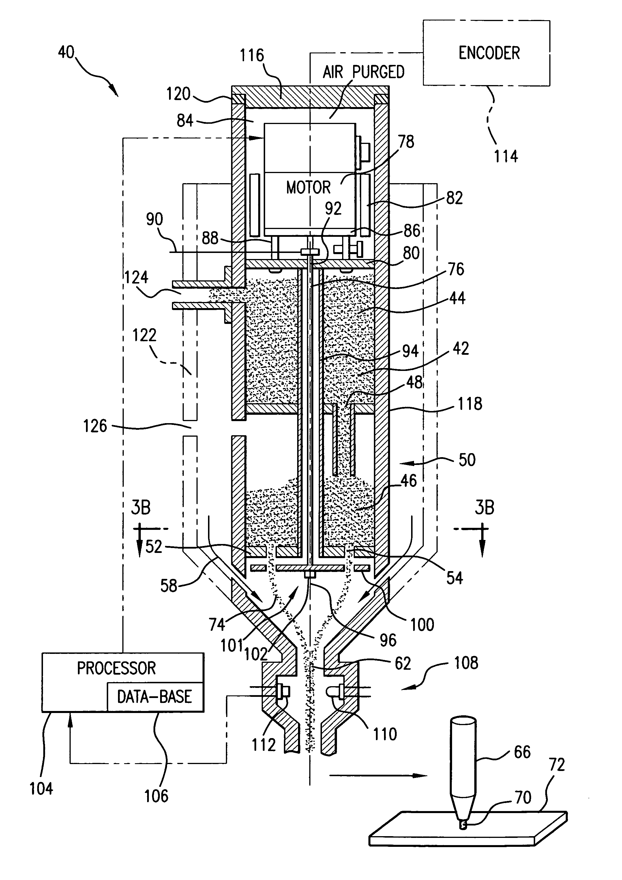
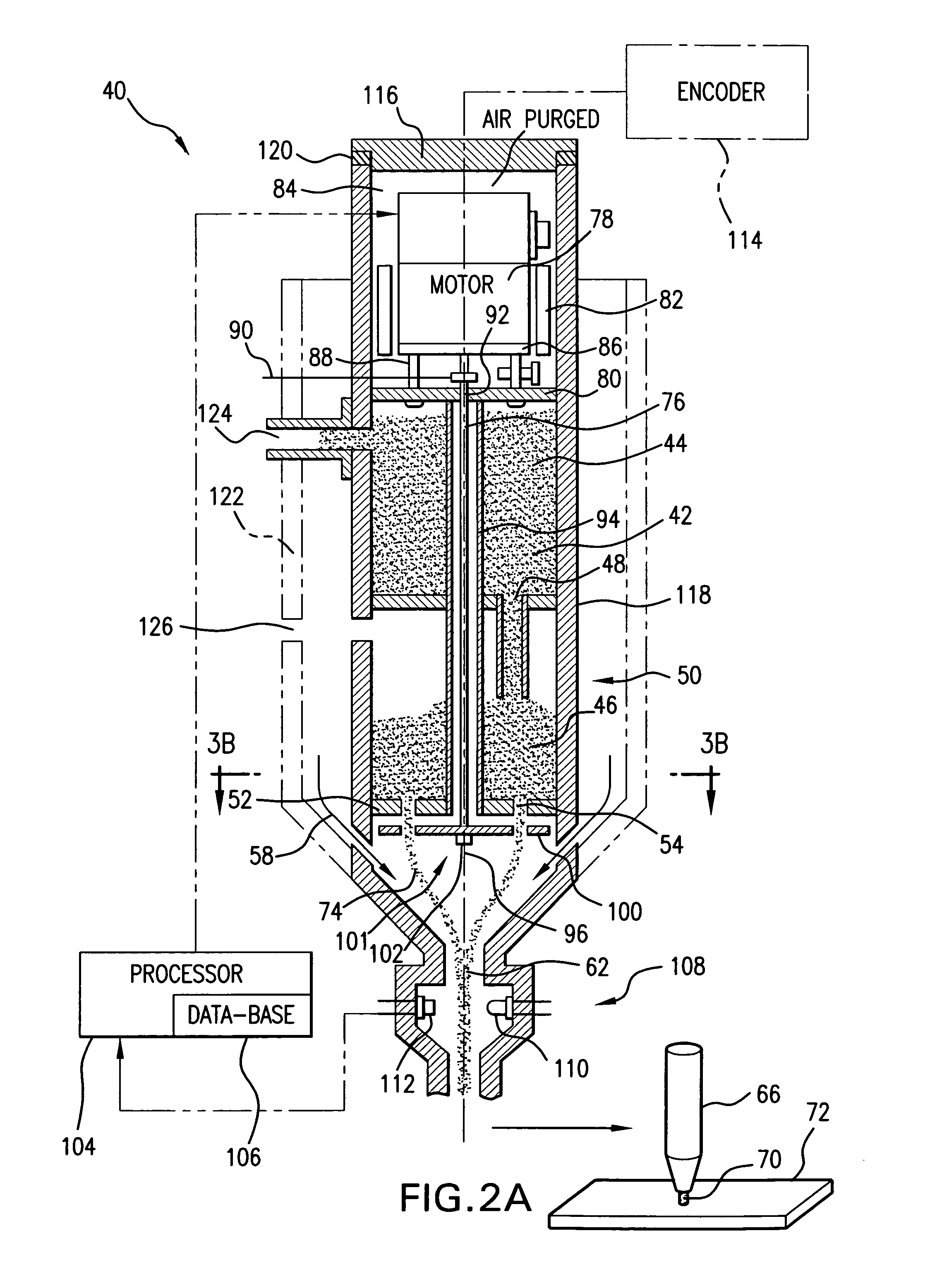
[0078]In one example, the abrasive jet apparatus 40 formed in accordance with a preferred embodiment of the present invention typically exhibits the following advantages and characteristics, which are listed purely for illustrative, not limiting, purposes:

[0079]

(1) Linear range(a)excellent linearity, enhanced with the arc edgesmodifications;(b)full analog range: from 0 to more than 1000 gramsper minute;(2) CNC controlled servomotor(a)encoder position feedback;(b)instant response (non-pneumatic);(c)single variable throw actuator, (avoiding open / closecylinders of prior art abrasive water jet machines);(3) Sealed housing(a)internally aspirated vacuum line;(b)IP 67 wash down service;(4) Wear resistant coatings and materials; and,(5) Abrasive material dispensing valve(a)rotary shutter motion is mechanically simple;(b)self-clearing action;i.abrasive on shutter is centrifugally slung off;ii.no abrasive accumulates near the driveshaft / guide tube clearance;(c)drive shaft may have an integral...


PUM

PropertyMeasurementUnit
flow rateaaaaaaaaaa
displacementaaaaaaaaaa
abrasiveaaaaaaaaaa

Abstract

An abrasive jet apparatus is provided which includes an abrasive dispenser defining a compartment for storing a granular abrasive material and at least one metering orifice disposed in open communication therewith for dispensing the granular abrasive material. The apparatus also includes a shutter assembly disposed adjacent the metering orifice, which includes a shutter member angularly displaceable between first and second positions relative to the metering orifice. The shutter member has formed therethrough at least one shutter opening which in the first position is substantially fully aligned with the metering orifice, and in the second position is substantially fully offset therefrom. The apparatus further includes a position actuator operatively coupled to the shutter mechanism for reversibly displacing the shutter member to the first and second positions and a plurality of intermediate positions therebetween for occluding a selective portion of the metering orifice. A flow rate of the abrasive material dispensed through said metering orifice is thereby maintained at a predetermined level.

Description

REFERENCE TO RELATED APPLICATIONS[0001]This Utility Patent Application is based on Provisional Patent Application No. 60 / 537,036, filed 20 Jan. 2004.BACKGROUND OF THE INVENTION[0002]1. Field of the Invention[0003]The present invention relates to abrasive jet machines used to cut or otherwise machine process various materials by generating a focused stream of fluid mixed with abrasive particles. The present invention relates in particular, to abrasive jet machines which use a pressurized liquid as the driving fluid to propel the abrasive particles for cutting or other machining operation.[0004]The present invention is further related to an abrasive waterjet apparatus with a variable flow rate of an abrasive material to be entrained within the given fluid jet, wherein the flow rate is adaptively modulated to suit a particular operation of such apparatus.[0005]Also, the present invention is related to an abrasive jet apparatus having an automatically controlled metering orifice for the...

Claims


Application Information

Patent Timeline
Patent Type & Authority Patents(United States)
IPC IPC(8): B24B1/00
CPCB24C5/02B24C7/0053B24C7/0092B24C7/0076Y10S239/08Y10T83/0591Y10T83/364
Inventor PANUSKA, BRIAN R.HAMMER, JOSEPHHAMMER, RONALDBACHMAN, WESLEY
Owner LAI INT
Why Eureka
Try Eureka