Hand-held, hand operated power syringe and methods

a hand-held, power syringe technology, applied in the direction of medical syringes, infusion devices, intravenous devices, etc., can solve the problems of increasing the manufacturing cost of hand-held power syringes, complex ratcheting mechanisms, and difficult device use, so as to maximize the amount of leverage

Inactive Publication Date: 2006-05-09
PMT PARTNERS
View PDF25 Cites 91 Cited by
  • Summary
  • Abstract
  • Description
  • Claims
  • Application Information

AI Technical Summary

Benefits of technology

[0012]The handle of the fluid delivery apparatus resembles a scissors and includes two members, a first of which is configured to be held by the fingers of an individual and the second of which is configured to be held by the individual's thumb or positioned against the palm of the individual. One or both of the first and second handle members may be bent so as to enable a user to grip both members with one hand while maximizing the amount of leverage provided as the handle members are forced toward one another.

Problems solved by technology

Due to the increase in delivery force provided by fluid delivery devices, such devices are particularly useful for injecting high viscosity fluids, which would otherwise be difficult, if not impossible, to inject by forcing one's thumb against the plunger of a conventional hand-held syringe.
Ratcheting mechanisms are, however, often complex and, consequently, add to the manufacturing costs of such hand-held power syringes.
Nonetheless, such a syringe only assists the user in forcing the plunger into the syringe barrel by transferring the location where force must be applied and increasing the area of a member to which force must be applied.
Nonetheless, these fluid delivery devices may be difficult to use when the injection of high viscosity fluids is required, which may cause physical or mental discomfort to a patient into whom the fluid is being injected.
Nonetheless, due to the manner in which the increased amount of force is applied, it is difficult for a user to make fine adjustments when injecting fluid into a body or extracting fluid therefrom.

Method used


Image

  • Hand-held, hand operated power syringe and methods
  • Hand-held, hand operated power syringe and methods
  • Hand-held, hand operated power syringe and methods

Examples


Embodiment Construction

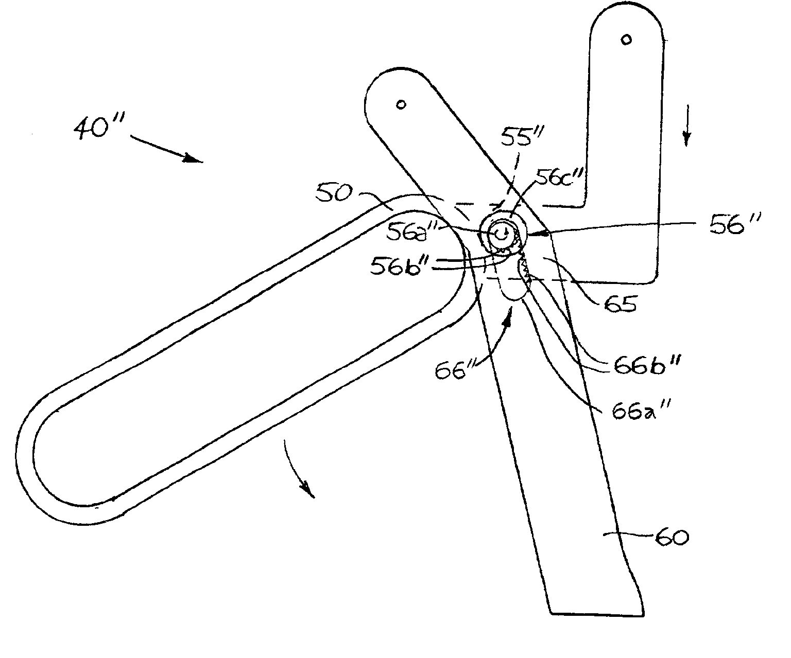
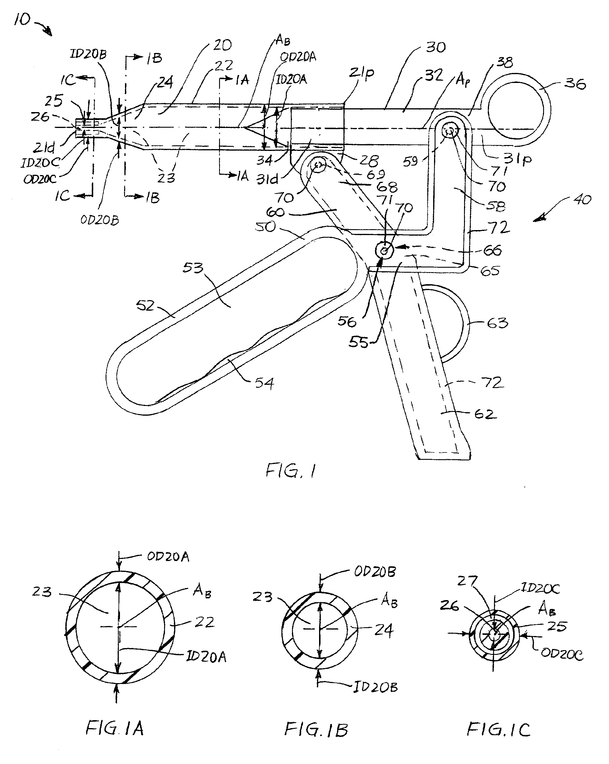
[0029]FIG. 1 illustrates an exemplary embodiment of a fluid delivery apparatus, or power syringe 10, incorporating teachings of the present invention. Power syringe 10 includes a barrel 20, a plunger 30 associated with barrel 20, and a scissor-grip handle 40 which causes plunger 30 to move longitudinally relative to barrel 20. One or both of barrel 20 and plunger 30 may be removable from handle 40 to facilitate the replacement of these elements and the reuse of handle 40.

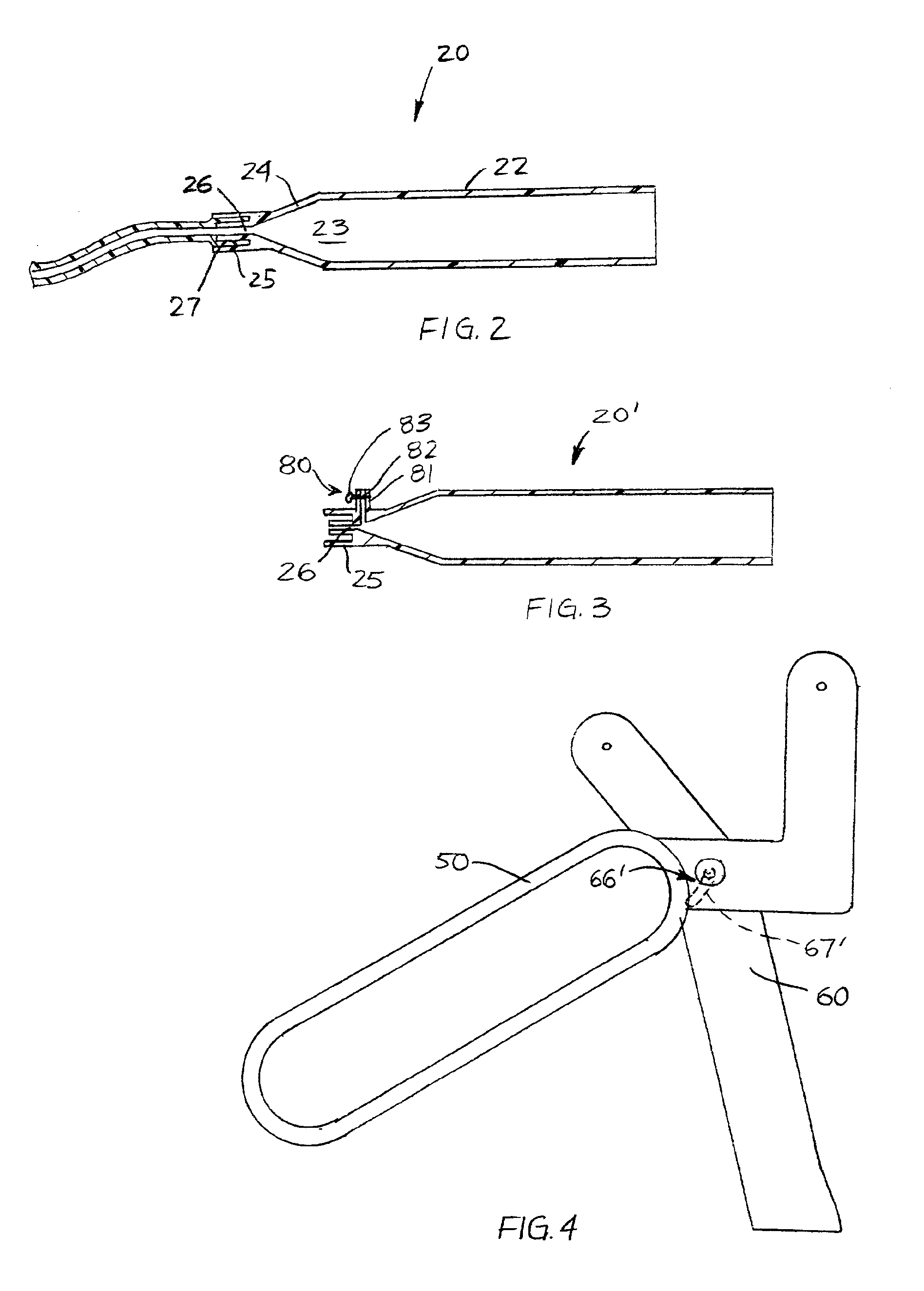
[0030]Barrel 20 of power syringe 10 is an elongate member with a hollow interior extending through the length thereof. Along the majority of its length, barrel 20 is substantially uniform in both cross-sectional shape and cross-sectional dimensions. The region of barrel 20 having such substantial cross-sectional uniformity is referred to herein as body 22. As depicted, body 22 extends from a proximal end 21p of barrel 20 to a tapered section or region 24 thereof. A syringe tip 25 is located on the opposite side of t...


PUM


Abstract

A hand-held power syringe. The power syringe includes a handle with pivotally connected first and second members. The first member is also pivotally connectable to a syringe barrel, while the second member is pivotally connectable to a syringe plunger. These three pivotal connections provide leverage for forcing high viscosity fluids into and out of a receptacle of the syringe barrel. One or both of the first and second members of the handle may be bent to facilitate a user's gripping and movement of the first and second handle members. The power syringe may be used in any suitable injection, infusion, or sample-obtaining application, including angiography and angioplasty.

Description

BACKGROUND OF THE INVENTION[0001]1. Field of the Invention[0002]The present invention relates generally to apparatus for facilitating the movement of a plunger of a syringe through a barrel of the syringe and, more particularly, to hand-held, hand operated apparatus that facilitate the movement of a plunger through a syringe barrel. More specifically, the present invention relates to hand-held apparatus with scissor grip type leveraged triggering systems that force a plunger of a syringe through the length of the barrel of the syringe.[0003]2. Background of Related Art[0004]Apparatus that facilitate the ejection of fluids from syringes are well known. Such apparatus are often referred to as fluid delivery devices or power syringes.[0005]Conventionally, fluid delivery devices have been used to inject liquids, such as contrasting media (e.g., dyes, carbon dioxide, etc.) and medicines into patients. With many fluid delivery devices, the rate at which a fluid is injected into a patient'...

Claims


Application Information

Patent Timeline
Patent Type & Authority Patents(United States)
IPC IPC(8): A61M5/00A61M5/142A61M5/315
CPCA61M5/007A61M5/31581A61M5/1782A61M5/204A61M5/3137A61M2005/3114A61M5/31511
Inventor FOJTIK, SHAWN P.
Owner PMT PARTNERS
Why Eureka
Try Eureka