Phased array knee coil

a phased array and knee coil technology, applied in the field of medical imaging systems, can solve the problems of large coil, no useful information, and reduced signal-to-noise ratio (snr or s/n), and achieve the effect of reducing sensitivity and image resolution, and reducing the size of the coil

Active Publication Date: 2006-05-09
GENERAL ELECTRIC CO
View PDF11 Cites 158 Cited by
  • Summary
  • Abstract
  • Description
  • Claims
  • Application Information

AI Technical Summary

Problems solved by technology

The magnetic moments point in the direction of the main magnetic field in a steady state, but produce no useful information if these magnetic moments are not disturbed by any excitation.
A large coil, however, produces lower signal-to-noise ratio (SNR or S / N) if it is also used for reception, mainly because of its greater distance from the signal-generating tissues being imaged.
Thus, a decrease in sensitivity and image resolution results.

Method used


Image

  • Phased array knee coil
  • Phased array knee coil
  • Phased array knee coil

Examples


Embodiment Construction

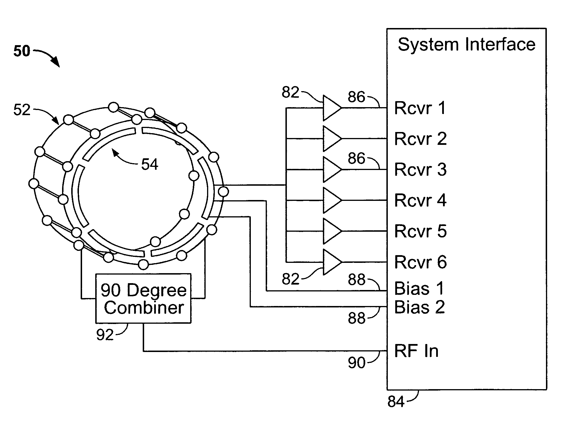
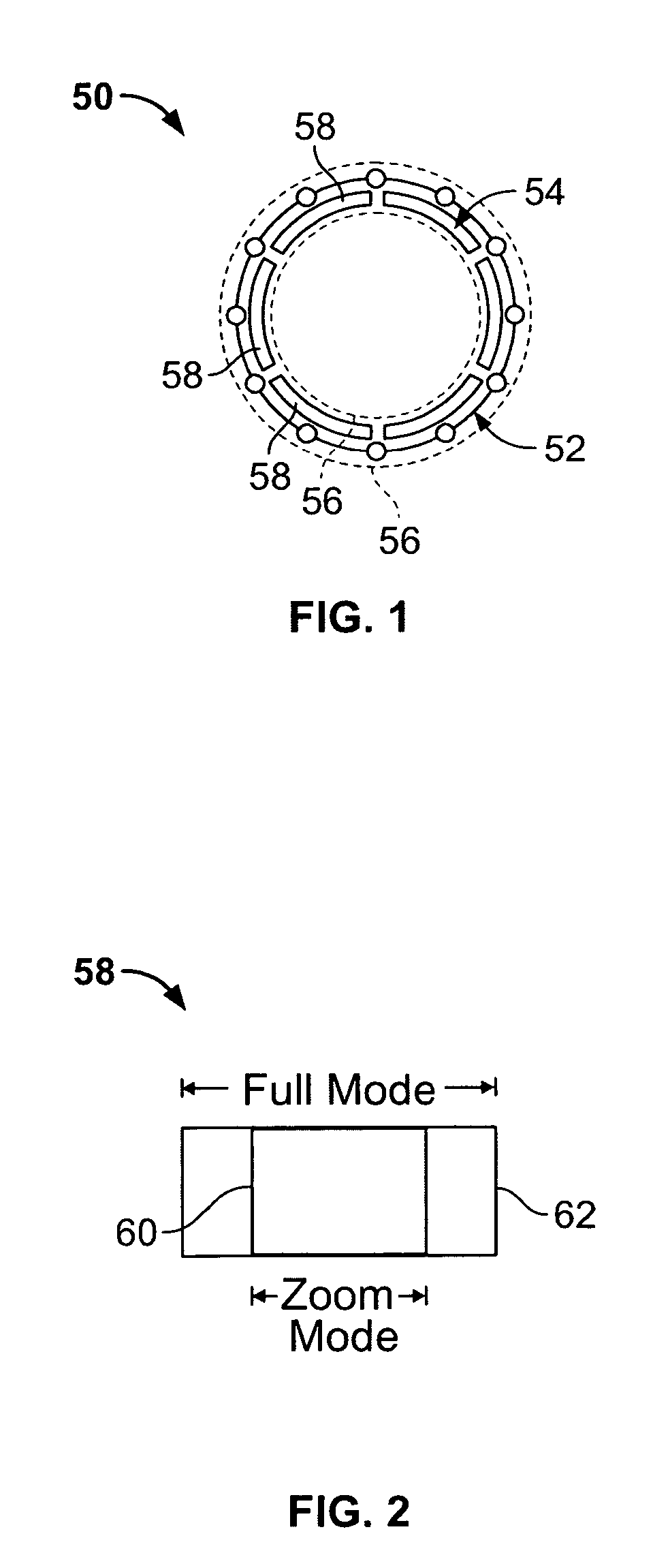
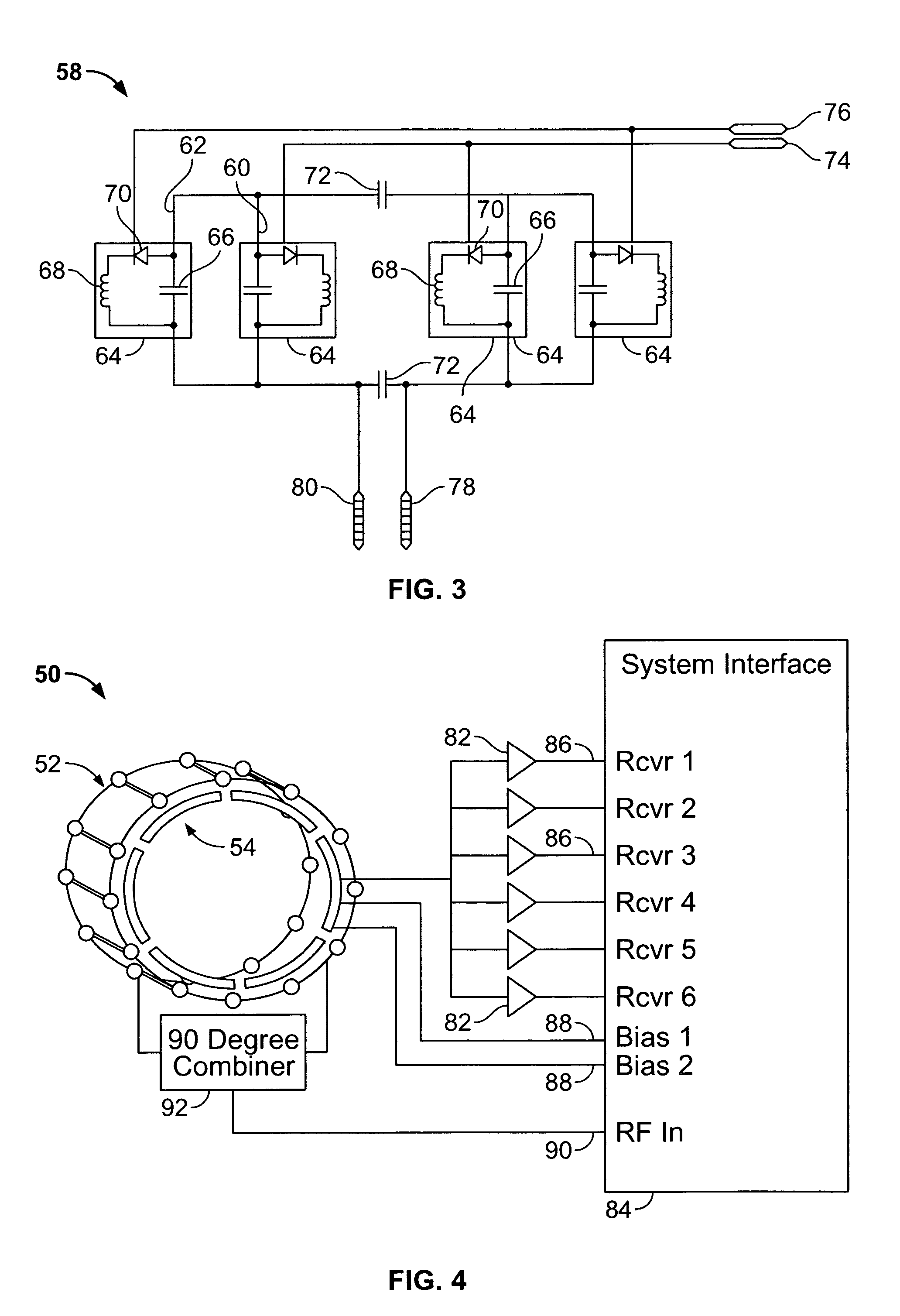
[0016]Various embodiments of the present invention provide a dual-coverage transmit / receive (T / R) phased array knee coil for a Magnetic Resonance Imaging System (MRI). The T / R phased array knee coil generally provides a first mode of operation or first imaging mode, in particular a zoom mode, that has a first S / I coverage, for example, about ten cm, and a second mode of operation or second imaging mode, in particular, a full coverage mode, having a second S / I coverage, for example, about sixteen cm. Smaller field-of-view (FOV) knee imaging can be performed without loss of SNR. Thus, a T / R phased array knee coil array is provided that is configured having a first mode of operation and a second mode operation, with a corresponding field-of-view provided for each mode of operation.

[0017]Specifically, and as shown in FIG. 1, the dual-coverage T / R phased array knee coil 50 generally includes a transmit coil array 52 and an array of receive coils 54. In an exemplary embodiment, the transm...


PUM


Abstract

A phased-array knee coil is provided and includes a transmit coil array and a receive coil array having a plurality of coils configured to provide a first imaging mode and a second imaging mode.

Description

CROSS REFERENCE TO RELATED APPLICATIONS[0001]This application claims priority to and the benefit of the filing date of U.S. Provisional Application No. 60 / 571,223, filed on May 14, 2004 and U.S. Provisional Application No. 60 / 523,660, filed on Nov. 19, 2003, both of which are hereby incorporated by reference in their entirety.BACKGROUND OF THE INVENTION[0002]This invention relates generally to medical imaging systems, and more particularly, to a knee coil array for a Magnetic Resonance Imaging (MRI) system.[0003]MRI or Nuclear Magnetic Resonance (NMR) imaging generally provides for the spatial discrimination of resonant interactions between Radio Frequency (RF) waves and nuclei in a magnetic field. Specifically, MRI utilizes hydrogen nuclear spins of the water molecules in the human body, which are polarized by a strong, uniform, static magnetic field of a magnet. This magnetic field is commonly referred to as B0 or the main magnetic field. The magnetically polarized nuclear spins g...

Claims


Application Information

Patent Timeline
Patent Type & Authority Patents(United States)
IPC IPC(8): G01V3/00G01R33/3415G01R33/54G01R33/56
CPCG01R33/3415G01R33/5604G01R33/4833
Inventor ZHENG, TSINGHUAZHAO, SHURENANDERSON, ROBERTPETROPOULOS, LABROS
Owner GENERAL ELECTRIC CO
Why Eureka
Try Eureka