Electromagnetic actuator with controlled attraction force

a technology of magnetizing force and actuator, which is applied in the direction of magnetic bodies, electrical devices, cores/yokes, etc., can solve the problems of large setback compared with residual space, and achieve the effect of increasing the total air gap that the flux needs to cross in the first zone, negligible influence on the performance of the actuator, and increasing the total air gap

Inactive Publication Date: 2006-05-09
VALEO SYST DE CONTROLE MOTEUR
View PDF23 Cites 3 Cited by
  • Summary
  • Abstract
  • Description
  • Claims
  • Application Information

AI Technical Summary

Benefits of technology

[0013]Thus, when the face of the armature is remote from the face of the core at a distance which is large compared with the setback of the set-back portion, the value of the flux in the core is determined mainly by the distance between the armature and the core, such that the set-back portion has only negligible influence on the performance of the actuator. When the armature comes close to the core, the setback of the set-back portion becomes large compared with the residual space that remains between the facing faces. The total air gap that the flux needs to cross in the first zone is thus increased. For given current, the force of attraction exerted by the coil on the armature is thus decreased.
[0014]Thus, for power supply electronics having the same feed, this embodiment tends to make it possible to reduce the force of attraction at the end of a stroke, such that the armature may come against the core more slowly and the clattering noise may be eliminated. This embodiment thus may make it possible to increase the extent to which the force of attraction is varied for a given variation in current.
[0015]It should be observed that the presence of set-back portions tends to lead to a corresponding increase in the holding current needed for holding the armature against the core. By acting on the relative areas of the first and second zones, it is thus possible to achieve a compromise between the looked-for reduction in force at the end of a stroke and the corresponding increase in current for holding the armature against the core.
[0022]This disposition avoids flux migrating into the second zone where it could become established more easily, thereby reducing the effectiveness of the set-back portions.

Problems solved by technology

When the armature comes close to the core, the setback of the set-back portion becomes large compared with the residual space that remains between the facing faces.

Method used


Image

  • Electromagnetic actuator with controlled attraction force
  • Electromagnetic actuator with controlled attraction force
  • Electromagnetic actuator with controlled attraction force

Examples


first embodiment

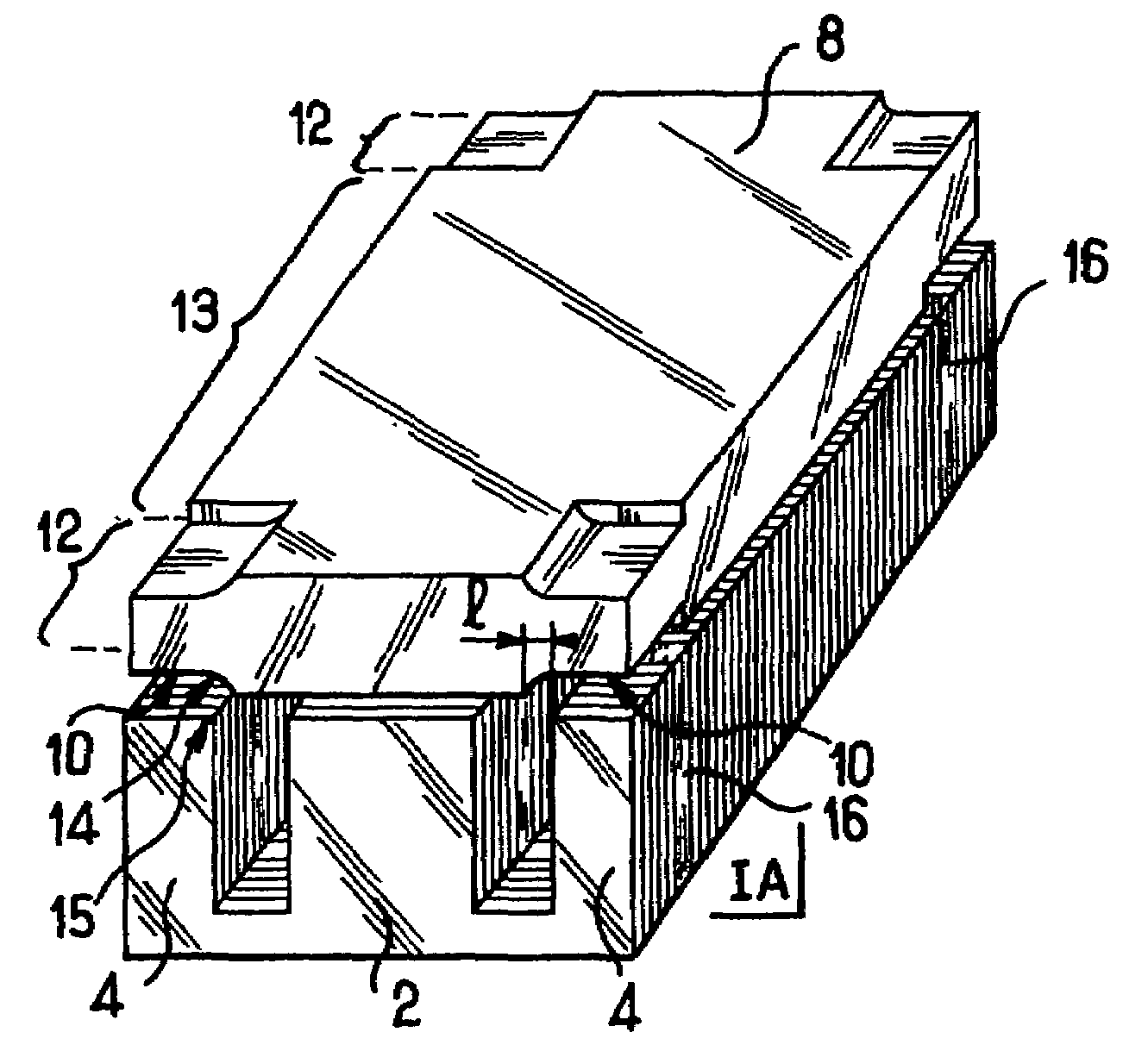
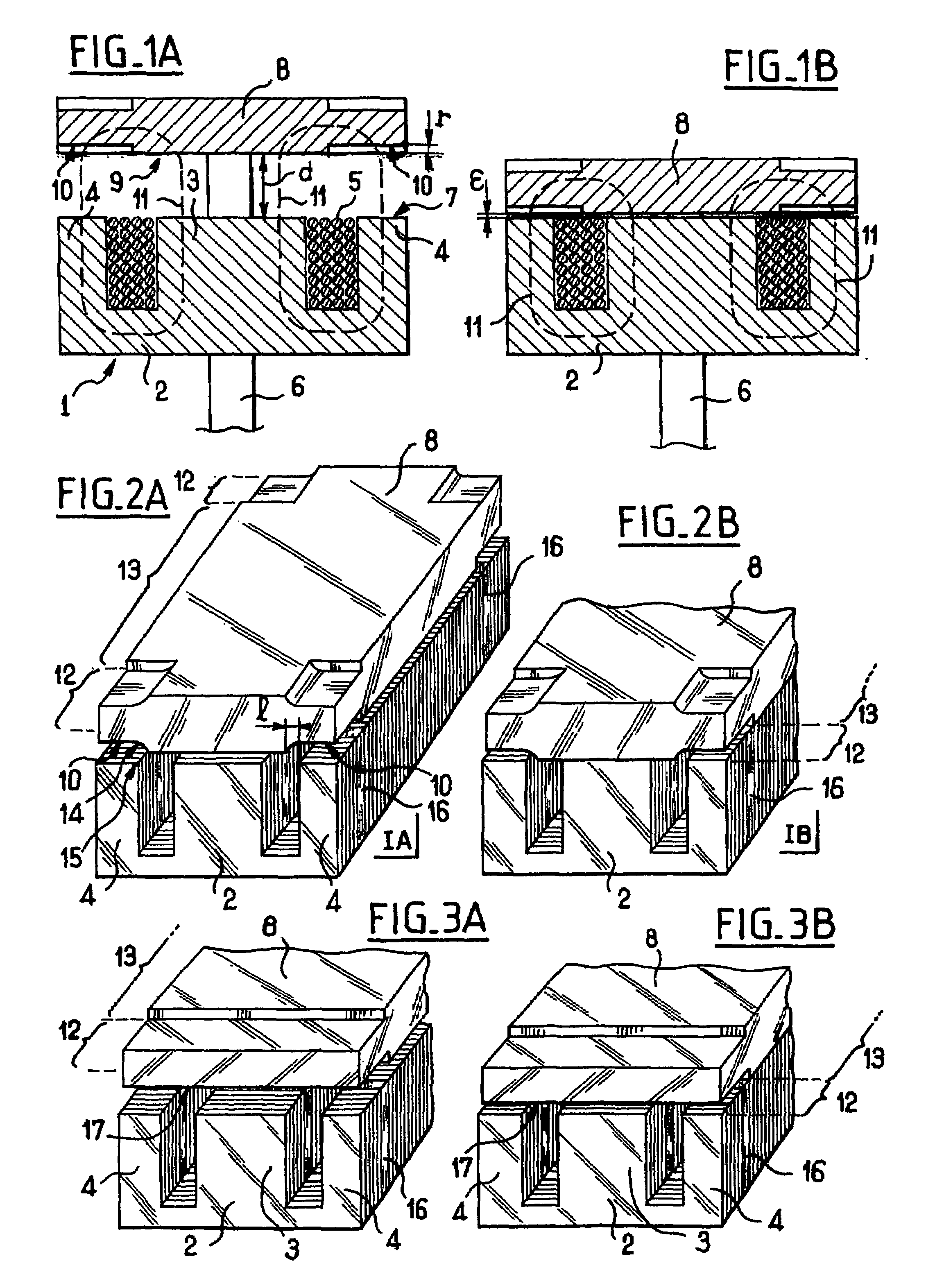
[0037]In the invention, each of the faces of the armature 8 presents four adaptation portions 10 each set back by a set-back distance r from the face that includes the set-back portion 10 in question. Each of the set-back portions 10 lies facing one of the side branches 4 of the core 2, and the set-back portions are disposed symmetrically about the actuator rod 6.

[0038]In the figures, the set-back portions 10 are shown on both faces of the armature 8 since the armature 8 co-operates in like manner with another coil (not shown) which extends facing the other face of the armature 8. For the purposes of description, only the set-back portions 10 made in the face 9 facing the core are taken into consideration.

[0039]In the position shown in FIG. 1A, the armature 8 is remote from the core 2, and the setback r of the set-back portion 10 is negligible compared with the distance d and measured between the face 9 of the armature 8 and the face 7 of the core 2. The total air gap to be crossed ...

second embodiment

[0053]In a second embodiment as shown in FIGS. 3A and 3B, the set-back portions are formed by steps 17 which extend transversely facing the central branch 3 and the side branches 4 of the core 2. In this case, the setback of the set-back portion has an effect on the flux not only where it passes between a side branch and the armature, but also where it passes between the central branch and the armature.

[0054]A step 17 is easier to machine than the set-back portions 10 shown in FIGS. 2A and 2B, and it avoids any risk of magnetic flux passing in unwanted manner via the internal edges 15 of the side branches 4.

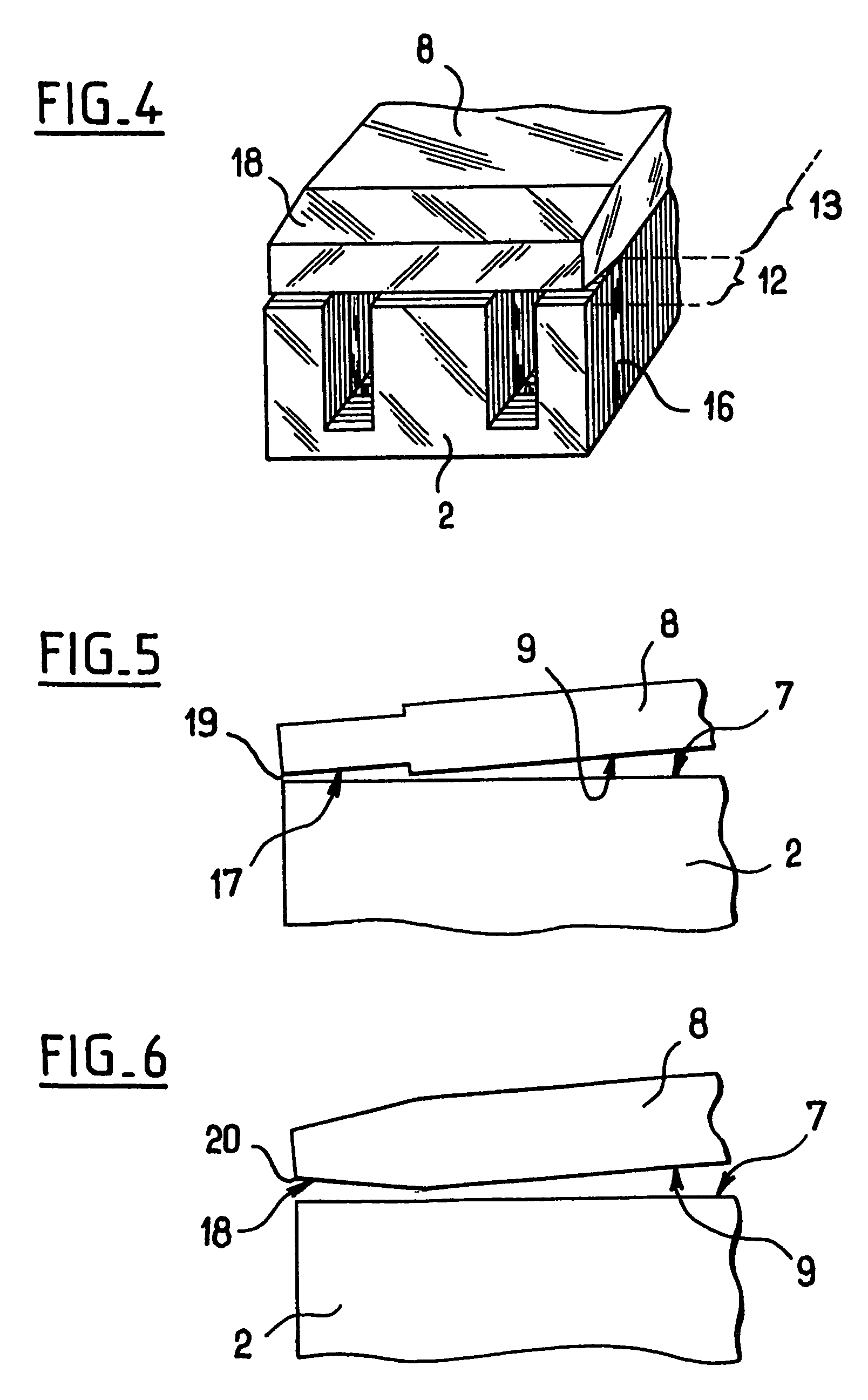
[0055]The step 17 defines two zones 12 and 13 in the same manner as in the above embodiment. In the zone 12 corresponding to the step 17 and in order to be looped, the flux needs to cross the setback r of the step 17 once in the air gap corresponding to the central branch 3 and once again in the air gap with one or other of the side branches. For a reduction in the force of attra...


PUM

PropertyMeasurementUnit
set-back distanceaaaaaaaaaa
magnetic fluxaaaaaaaaaa
magneticaaaaaaaaaa

Abstract

The invention relates to an electromagnetic actuator comprising an actuator member (6) connected to an armature (8) which is movable under drive from a drive member comprising at least one coil (1) for generating magnetic flux in a core (2) having a face facing a face of the armature (8), at least one of the facing faces including at least one set-back portion (10), the armature (8) and the core (2) being arranged, in a first zone (12) of the armature (8) and of the core (2) including the set-back portion, to define a first magnetic path which is interrupted by an air gap that is not less than the setback of the set-back portion (10) when the armature (8) bears against the core (2), and in a second zone (13) of the armature (8) and of the core (2) excluding the set-back portion, to define a second magnetic path which is interrupted solely by a residual air gap when the armature (8) bears against the core (2), the total area of the set-back portion being no greater than an area that would bring the magnetic flux to saturation in the second zone of the armature.

Description

CROSS-REFERENCE TO RELATED APPLICATIONS[0001]This application is a National Stage of Application PCT / FR03 / 00658, filed Feb. 28, 2003, which claims priority to French patent application 02 02631 filed Mar. 1, 2002, the disclosures of which are incorporated herein by reference in their entirety.BACKGROUND[0002]The invention relates to an electromagnetic actuator, and finds particular use in direct current (DC) electromagnetic actuators for actuating engine valves.[0003]Electromagnetic actuators are known that comprise an actuator rod connected to an armature to form a moving assembly associated with a drive member that propels the moving assembly from one extreme position to another, the extreme positions corresponding to the valve being in its open and closed positions.[0004]The drive member comprises at least one coil fitted with a core, one face of the armature being adapted to come into contact with one face of the coil core when the valve is in one of its open or closed positions...

Claims


Application Information

Patent Timeline
Patent Type & Authority Patents(United States)
IPC IPC(8): H01F7/00H01F7/08H01F7/16H02K33/00
CPCH01F7/081
Inventor WALRAET, DAVID
Owner VALEO SYST DE CONTROLE MOTEUR
Why Eureka
Try Eureka