
Remote monitoring system for air conditioners

a monitoring system and air conditioner technology, applied in the direction of instruments, heating types, static/dynamic balance measurement, etc., can solve the problems of increasing the problem of difficulty in adjusting, requiring a prolonged period of time, and requiring a great deal of adjustmen

Inactive Publication Date: 2006-05-09
SANYO ELECTRIC CO LTD
View PDF15 Cites 115 Cited by
  • Summary
  • Abstract
  • Description
  • Claims
  • Application Information

AI Technical Summary

Benefits of technology

The present invention provides a system for remotely monitoring and adjusting air conditioners in buildings. The system includes a remote monitor and data collectors in each building. The remote monitor receives and collects data from the data collectors and prepares a diagnosis of the operating state of the air conditioner based on the data. The diagnosis is then transmitted to the remote monitor of the installation company. The installation company adjusts the air conditioner based on the diagnosis and the control parameters determined by the adjuster. The system allows for easy and efficient adjustment of air conditioners from a distance, optimizing control parameters and improving operating states.

Problems solved by technology

Accordingly, the air conditioner has the problem of necessitating a prolonged period of time and great labor for adjustment.
This problem becomes more serious in the case of air conditioners which are installed in a plurality of buildings since the conditioner in each building needs to be adjusted.

Method used


Image

  • Remote monitoring system for air conditioners
  • Remote monitoring system for air conditioners
  • Remote monitoring system for air conditioners

Examples


Embodiment Construction

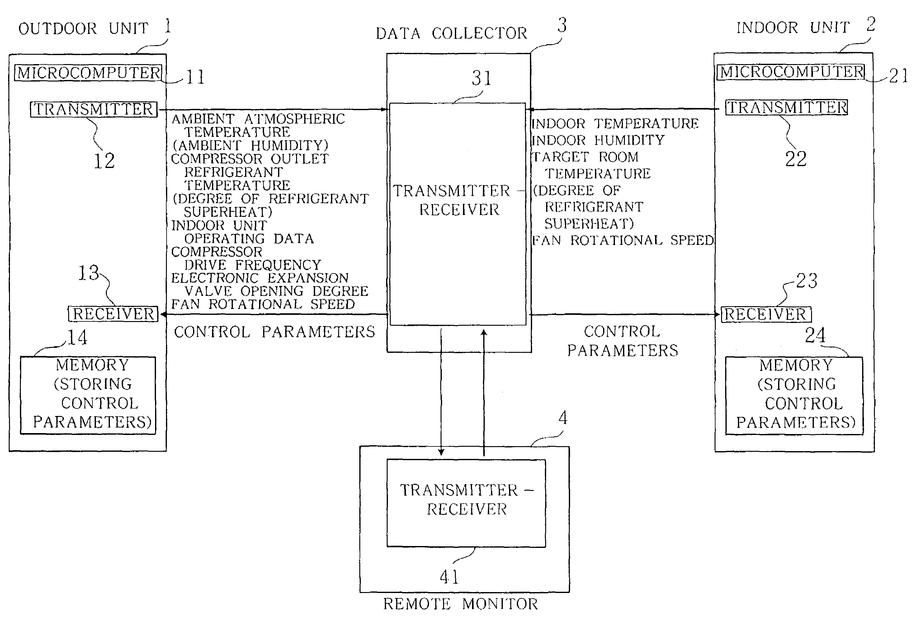
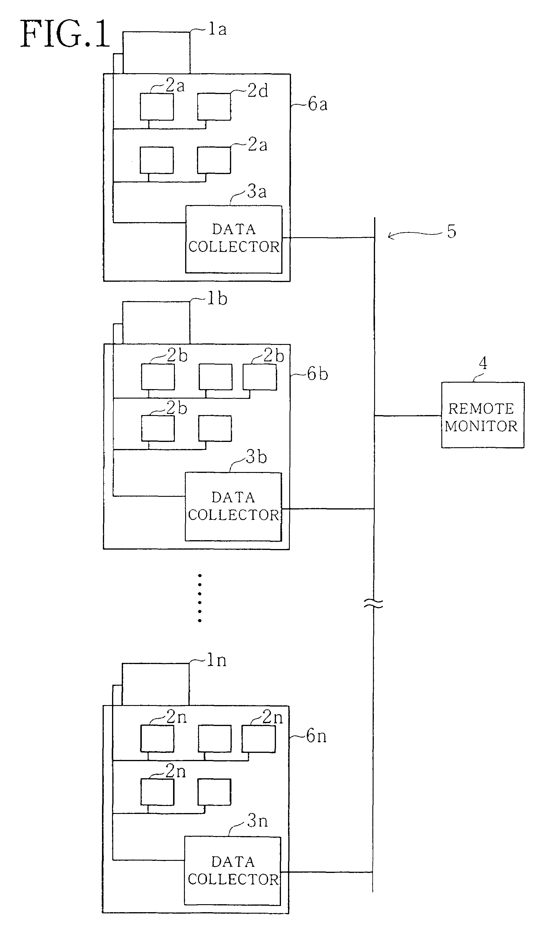
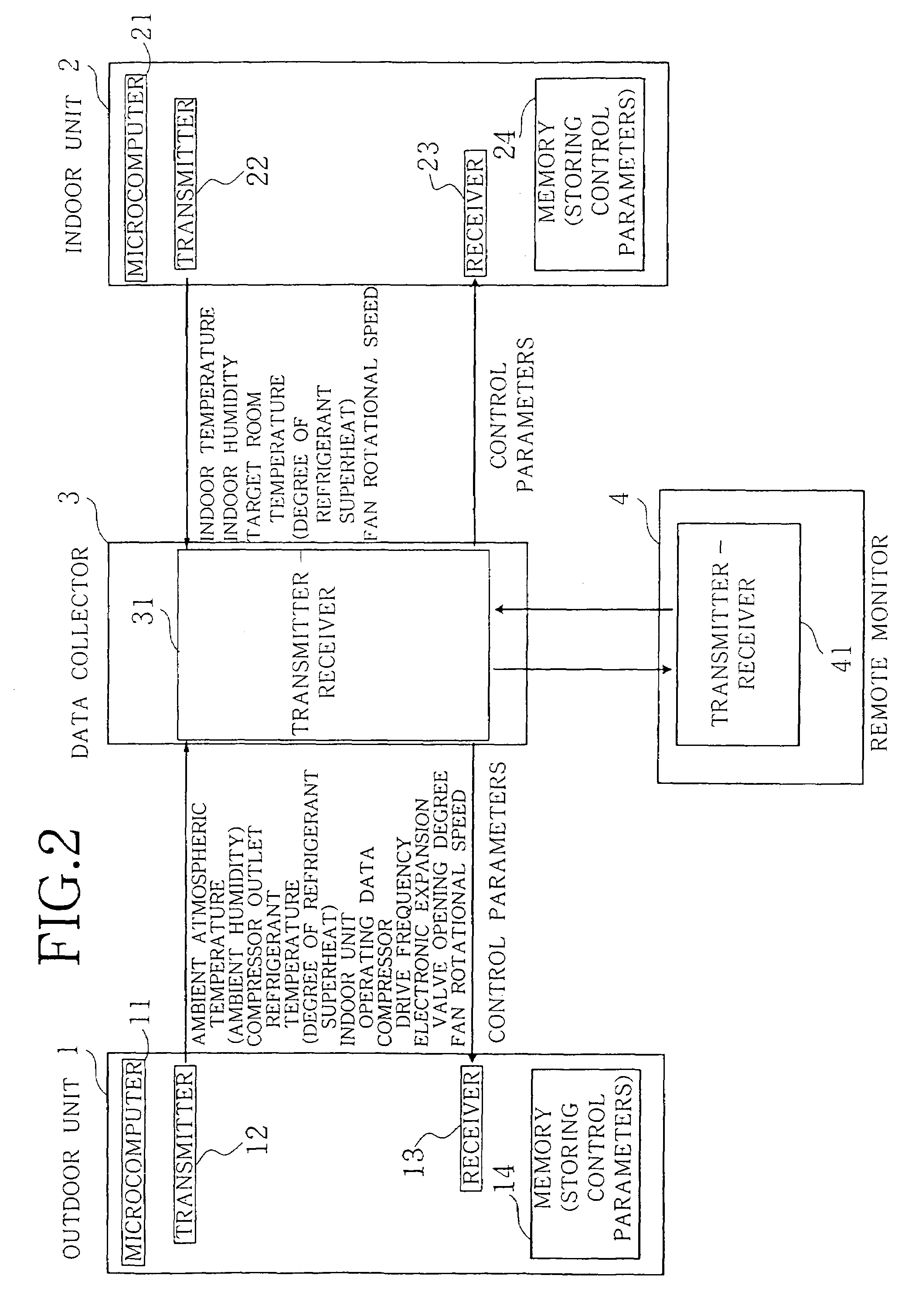
[0024]A detailed description will be given of an embodiment of the present invention with reference to the drawings. The remote monitoring system of the invention is adapted for use with air conditioners. As shown in FIG. 1, a plurality of buildings 6a, 6b, . . . , 6n have one or a plurality of outdoor units 1a, 1b, . . . , 1n installed on the rooftop of the building and one or a plurality of indoor units 2a, 2b, . . . , 2n installed in a room or rooms thereof. The buildings 6a, 6b, . . . , 6n are provided with data collectors 3a, 3b, . . . , 3n for collecting state data representing the operating state of the outdoor unit and indoor unit installed in the building. The data collectors 3a, 3b, . . . , 3n of the buildings 6a, 6b, . . . , 6n are connected to a remote monitor 4 installed in the building of the air conditioner installation company via internet, telephone network or like communication network 5.

[0025]The outdoor unit 1 shown in FIG. 2 has incorporated therein a microcompu...


PUM


Abstract

This invention provides a remote monitoring system for air conditioners installed respectively in a plurality of buildings for concentrically monitoring the operating state of the air conditioners from a distance. The system comprises data collectors 3 installed in the respective buildings, and a remote monitor 4 connected to the data collectors 3 of all the buildings via a communication network. Each of the data collectors 3 collects state data representing the operating state of the air conditioner installed in each building and transmits the collected state data to the remote monitor 4. The remote monitor 4 receives the state data collected by each data collector 3, diagnoses the operating state of the air conditioner installed in each building based on the received state data, and outputs the result of diagnosis. In this way, the air conditioners can be optimally adjusted within a short period of time.

Description

RELATED APPLICATION[0001]This application is a Continuation-In-Part Application of application Ser. No. 09 / 820,170 filed on Mar. 29, 2001 now abandoned.FIELD OF THE INVENTION[0002]The present invention relates to a system for concentrically monitoring from a distance the operating state of air conditioners installed in a plurality of buildings, respectively.BACKGROUND OF THE INVENTION[0003]To adjust the room temperature and humidity of a building by an air conditioner, it is conventional practice to install one or a plurality of outdoor units on the rooftop of the building or externally of the building and one or a plurality of indoor units in each room of the building and to control the operation of the outdoor units and the indoor units in accordance with the outdoor temperature and humidity.[0004]For example after the air conditioner is started up, the indoor units and the outdoor units of the air conditioner have their operations so controlled as to cause the temperature of each...

Claims


Application Information

Patent Timeline
Patent Type & Authority Patents(United States)
IPC IPC(8): G05D23/00F24F11/00G05B23/02
CPCF24F11/0086G05B23/0294F24F2011/0067G05B2219/13F24F2011/0068F24F11/30F24F11/54F24F11/56G05B2223/06
Inventor MAEDA, TSUTOMUKAWAI, TSUYOSHIOZAWA, YOSHIO
Owner SANYO ELECTRIC CO LTD
Learn More