Vertical-mount electrical power distribution plugstrip

a plug-in, vertical-mount technology, applied in the direction of single network parallel feeding arrangement, dc source parallel operation, coupling device connection, etc., can solve the problems of consuming the vertical mounting space needed by the network appliances themselves, power-on reset, and tight space, and achieve the effect of freeing up vertical rackmount spa

Inactive Publication Date: 2006-05-09
SERVER TECHNOLOGY
View PDF46 Cites 176 Cited by
  • Summary
  • Abstract
  • Description
  • Claims
  • Application Information

AI Technical Summary

Benefits of technology

[0011]An advantage of the present invention is that an electrical power distribution plugstrip is provided that frees up vertical rackmount space for other equipment.
[0013]A further advantage of the present invention is that an electrical power distribution plugstrip is provided that allows a network console operator to control the electrical power status of a router or other network device.
[0014]A still further advantage of the present invention is that an electrical power distribution plugstrip is provided for reducing the need for enterprise network operators to dispatch third party maintenance vendors to remote equipment rooms and POP locations simply to power-cycle failed network appliances.

Problems solved by technology

So each TelCo typically rents space on their premises to the network providers, and such space is tight and very expensive.
Such cycling of operating power will force a power-on reset of the network appliance, and is sometimes needed when an appliance hangs or bombs.
Conventional power management equipment has either been mounted in the tops or bottoms of the server farm RETMA racks, and thus has consumed vertical mounting space needed by the network appliances themselves.

Method used


Image

  • Vertical-mount electrical power distribution plugstrip
  • Vertical-mount electrical power distribution plugstrip
  • Vertical-mount electrical power distribution plugstrip

Examples


Embodiment Construction

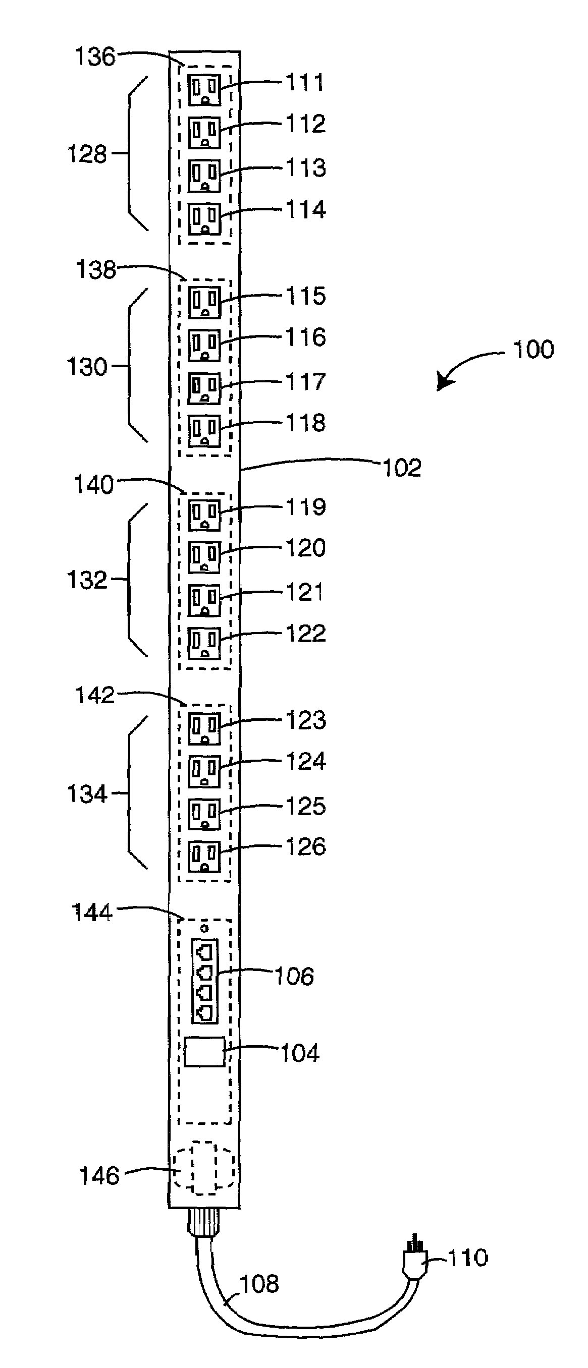
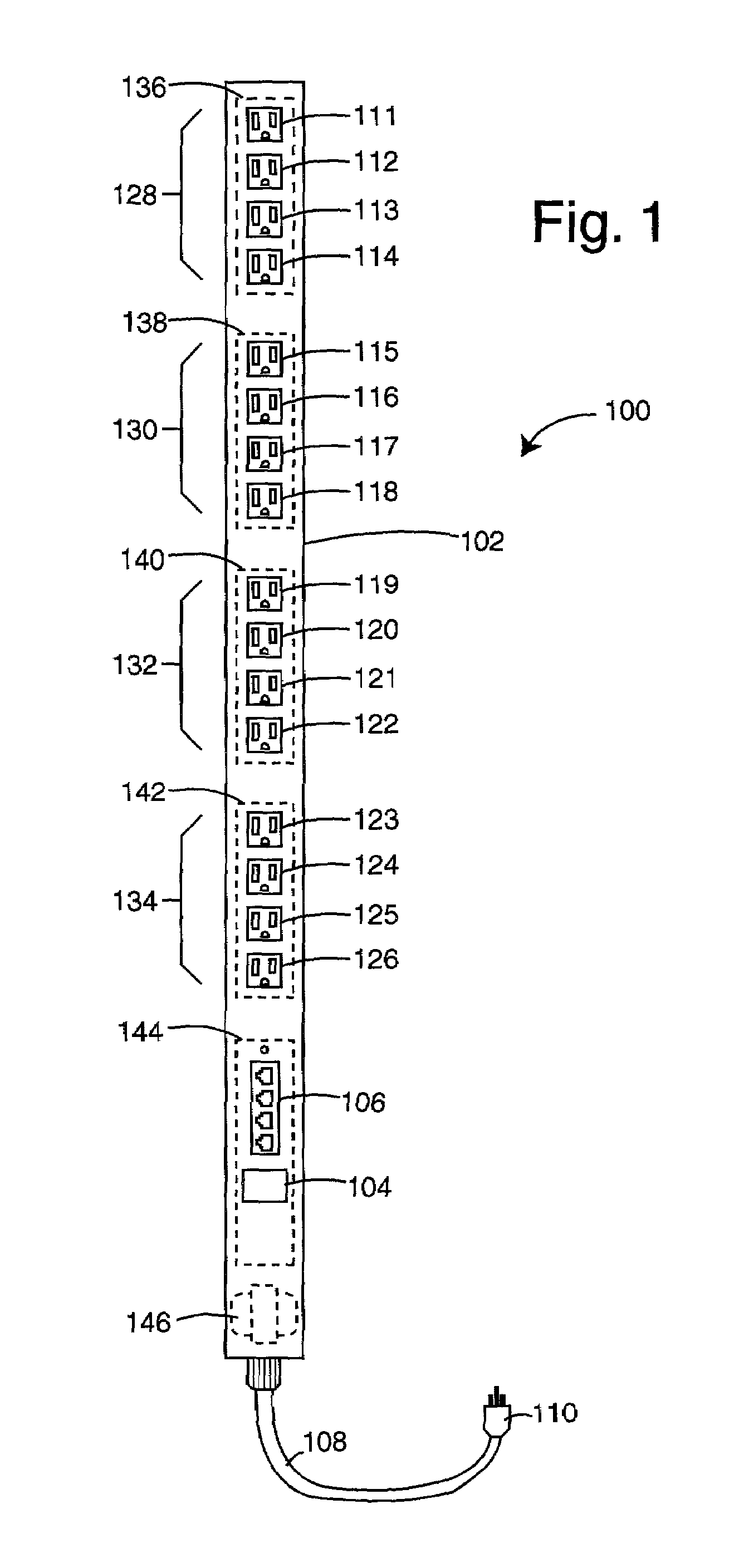
[0025]FIG. 1 represents an electrical power distribution plugstrip embodiment of the present invention, and is referred to herein by the general reference numeral 100. The electrical power distribution plugstrip 100 includes a long, thin housing 102 with one face having a user display 104 and a set of RJ-11 control jacks 106. A power input cord 108 is provided at one end and has an appropriate power plug 110. For example, the power plug 110 is rated for 125VAC at 30A. A plurality of power outlet sockets 111–126 are provided along a single face of the housing 102. The user display 104 preferably provides a digital readout of the total input current flowing in on power input cord 108.

[0026]The total input current display 104 can be used to advantage by a technician when installing or troubleshooting a RETMA equipment rack by watching how much current change is observed when each network appliance is plugged in and turned on. Unusually high or low currents can indicate particular kinds...


PUM


Abstract

A vertical-mount electrical power distribution plugstrip comprises a long, thin plugstrip body with several power outlet plugs distributed along the length of one face. A power input cord is provided at one end, and this supplies operating power to each of the power outlet plugs through individual relay control.

Description

CO-PENDING APPLICATIONS[0001]This Application is a continuation-in-part of U.S. patent application Ser. No. 09 / 732,557, filed Dec. 8, 2000, titled NETWORK-CONNECTED POWER MANAGER FOR REBOOTING REMOTE COMPUTER-BASED APPLIANCES.BACKGROUND OF THE INVENTION[0002]1. Field of the Invention[0003]The invention relates generally to remote power management systems, and more particularly to electrical power distribution devices and methods for conserving the primary rack-mount spaces in a standard RETMA rack.[0004]2. Description of the Prior Art[0005]Network server “farms” and other network router equipment have settled on the use of equipment bays in 19″ standard RETMA racks. Many of these server and router farms are located at telephone company (TelCo) central equipment offices because they need to tie into very high bandwidth telephone line trunks and backbones. So each TelCo typically rents space on their premises to the network providers, and such space is tight and very expensive.[0006]T...

Claims


Application Information

Patent Timeline
Patent Type & Authority Patents(United States)
IPC IPC(8): G06F15/173G06F1/26G06F1/32
CPCG06F1/26G06F1/3209G06F1/3246H02J3/14H02J13/0062H05K7/1492H02B1/34G06F1/266Y02B60/1296G06F2200/261H01R25/003Y02B70/3225Y02B90/226Y02B90/2638Y04S20/16Y04S20/222Y04S40/124H02J2310/12H02J13/00016H02J13/00004H02J13/0005Y02B90/20Y02D10/00Y04S20/00H01R24/64H01R24/76
Inventor EWING, CARREL W.AUCLAIR, BRIAN P.CLEVELAND, ANDREW J.MASKALY, JAMES P.MCGLUMPHY, DENNIS W.BIGLER, MARK J.
Owner SERVER TECHNOLOGY
Why Eureka
Try Eureka