Network power administration system

a power administration system and network technology, applied in the direction of digital computer details, dc source parallel operation, coupling device connection, etc., can solve the problems of power-on reset, consuming the vertical mounting space needed by the network appliances themselves, and tight space and high cos

Inactive Publication Date: 2005-09-15
SERVER TECHNOLOGY
View PDF62 Cites 99 Cited by
  • Summary
  • Abstract
  • Description
  • Claims
  • Application Information

AI Technical Summary

Benefits of technology

[0012] An advantage of the present invention is that a network remote power management outlet strip is provided that frees up vertical rackmount space for other equipment.
[0013] Another advantage of the present invention is that a network remote power management outlet strip is provided for controlling the operating power supplied to network appliances over computer networks, such as TCP / IP and SNMP.
[0014] A further advantage of the present invention is that a network remote power management outlet strip is provided that allows a network console operator to control the electrical power status of a router or other network device.
[0015] A still further advantage of the present invention is that a network remote power management outlet strip is provided for reducing the need for enterprise network operators to dispatch third party maintenance vendors to remote equipment rooms and POP locations simply to power-cycle failed network appliances.

Problems solved by technology

So each TelCo typically rents space on their premises to the network providers, and such space is tight and very expensive.
Such cycling of operating power will force a power-on reset of the network appliance, and is sometimes needed when an appliance hangs or bombs.
Conventional power management equipment has either been mounted in the tops or bottoms of the server farm RETMA racks, and thus has consumed vertical mounting space needed by the network appliances themselves.

Method used


Image

  • Network power administration system
  • Network power administration system
  • Network power administration system

Examples


Embodiment Construction

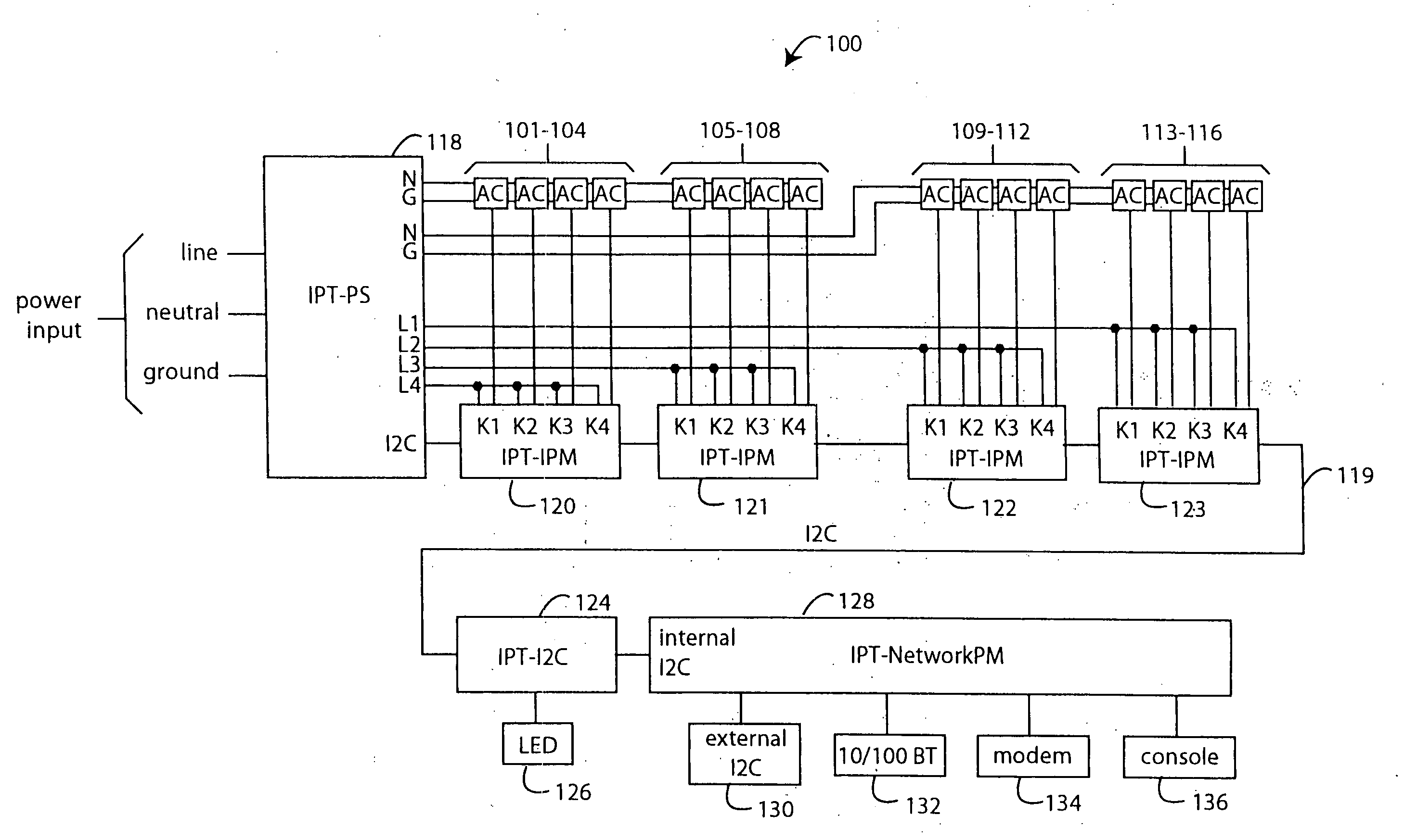
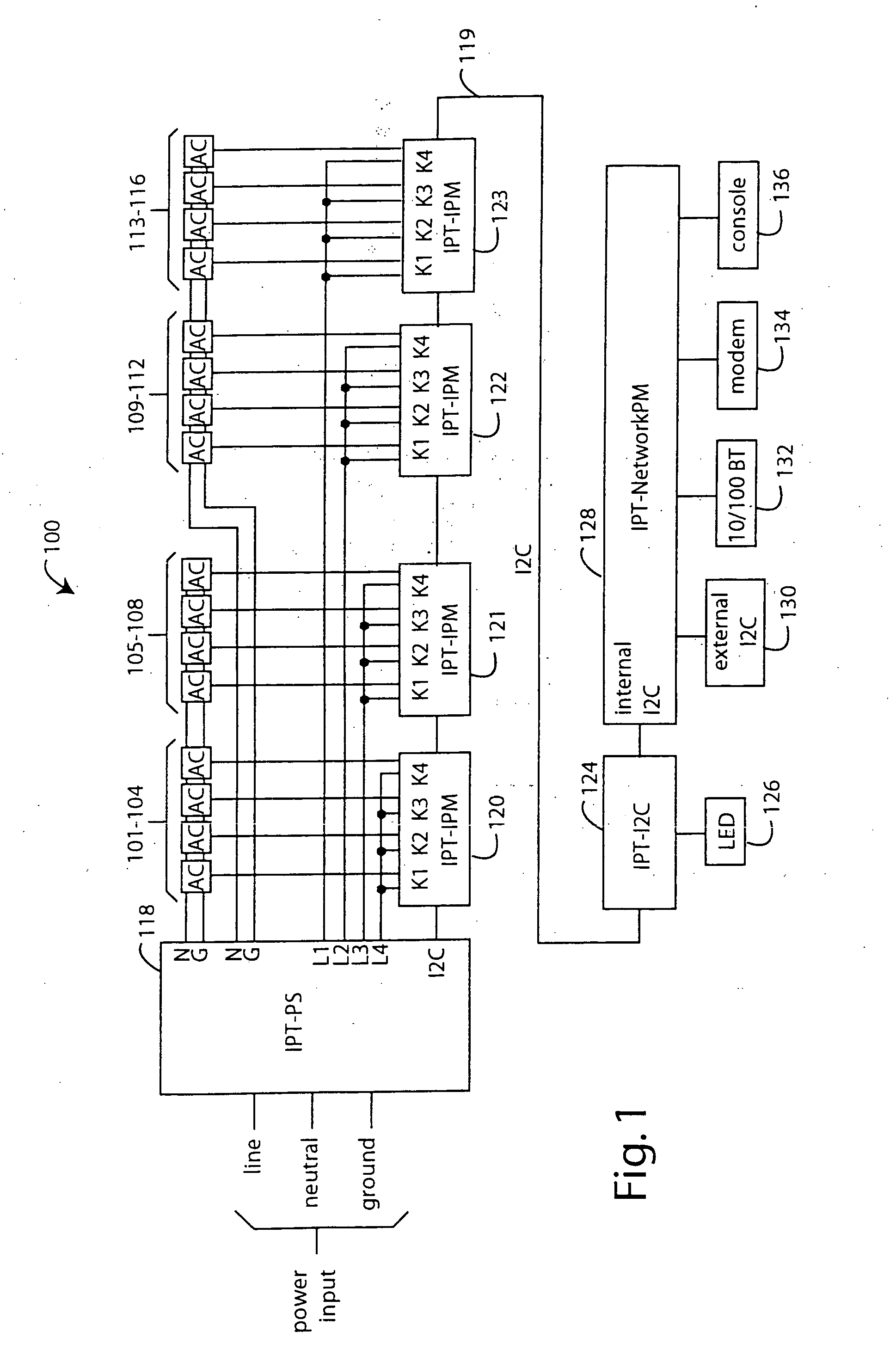
[0028]FIG. 1 represents a network remote power management outlet strip embodiment of the present invention, and is referred to herein by the general reference numeral 100. The outlet strip 100 provides independently managed power to each of sixteen AC-output receptacles 101-116. A power supply (IPT-PS) module 118 senses and totalizes the combined current delivered to all the AC-output receptacles 101-116 from its AC-power input.

[0029] Peripheral integrated circuits (IC's) that have to communicate with each other and the outside world can use a simple bi-directional 2-wire, serial data (SDA) and serial clock (SCL) bus for inter-IC (I2C) control developed by Philips Semiconductor. The I2C-bus has become a worldwide industry-standard proprietary control bus.

[0030] The IPT-PS module 118 digitally encodes the total AC-current information onto an internal I2C-bus 119. The IPT-PS module 118 supplies DC-operating power for the internal I2C-bus 119 which is derived from the AC-power input....


PUM


Abstract

A vertical-mount network remote power management outlet strip embodiment of the present invention comprises a long, thin outlet strip body with several independently controllable power outlet sockets distributed along its length. A power input cord is provided at one end, and this supplies AC-operating power to relays associated with each of the power outlet sockets. The relays are each addressably controlled by a microprocessor connected to an internal I2C-bus serial communications channel. The power-on status of each relay output to the power outlet sockets is sensed and communicated back on the internal I2C-bus. A device-networking communications processor with an embedded operating system translates messages, status, and controls between the internal I2C-bus and an Ethernet port, and other external networks.

Description

RELATED APPLICATIONS AND PATENTS [0001] This Application is a continuation of U.S. patent application Ser. No. 10 / 313,314, filed Dec. 16, 2002, and titled NETWORK REMOTE POWER MANAGEMENT OUTLET. Such in turn is a continuation-in-part of U.S. patent application Ser. No. 09 / 930,780, filed Aug. 15, 2001, published as US-2002-0002593-A1 on Jan. 3, 2002, and titled VERTICAL-MOUNT NETWORK REMOTE POWER MANAGEMENT OUTLET STRIP. Such is in turn a continuation-in-part of U.S. patent application Ser. No. 09 / 732,557, filed Dec. 8, 2000, titled NETWORK-CONNECTED POWER MANAGER FOR REBOOTING REMOTE COMPUTER-BASED APPLIANCES, that is a continuation-in-part of U.S. patent application Ser. No. 09 / 375,471, filed Aug. 16, 1999, titled REMOTE POWER CONTROL SYSTEM THAT VERIFIES WHICH DEVICES IS SHUT-DOWN BEFORE SUCH ACTION IS COMMITTED TO, which in turn is a continuation-in-part of U.S. patent application Ser. No. 08 / 685,436, that was filed on Jul. 23, 1996 and is titled, SYSTEM FOR READING THE STATUS AN...

Claims


Application Information

Patent Timeline
Patent Type & Authority Applications(United States)
IPC IPC(8): G06F1/26G06F1/32
CPCG06F1/26Y02B60/1296G06F1/3209G06F1/3246G06F2200/261H01R25/003H02J3/14H02J13/0062Y02B70/3225Y02B90/226Y02B90/2638Y04S20/16Y04S20/222Y04S40/124H01H47/00G06F1/266G06F13/364G06F13/4282H02J13/00016H02J13/0005Y02B90/20Y02D10/00Y04S20/00Y04S20/14H02J2310/60H02J2310/66G06F1/3287
Inventor EWING, CARREL W.AUCLAIR, BRIAN P.CLEVELAND, ANDREW J.MASKALY, JAMES P.MCGLUMPHY, DENNIS W.BIGLER, MARK J.
Owner SERVER TECHNOLOGY
Why Eureka
Try Eureka