EGR system for internal combustion engine provided with a turbo-charger

a technology of internal combustion engine and turbocharger, which is applied in the direction of machines/engines, mechanical equipment, electric control, etc., can solve the problems of increasing cost, increasing cost, and affecting the efficiency of turbines, so as to achieve efficient nox reduction and high egr rate

Inactive Publication Date: 2006-05-16
ISUZU MOTORS LTD
View PDF18 Cites 101 Cited by
  • Summary
  • Abstract
  • Description
  • Claims
  • Application Information

AI Technical Summary

Benefits of technology

[0008]The present invention has been made in order to solve the above-mentioned problems. The purpose of the invention is to provide an EGR system for an internal combustion engine provided with a turbo-charger which is able t

Problems solved by technology

However, the construction of the EGR passage has a problem that the EGR cannot be carried out as desired in a large type of internal combustion engine.
Therefore, the variable back pressure control valve has to be large in capacity, and this has been

Method used


Image

  • EGR system for internal combustion engine provided with a turbo-charger
  • EGR system for internal combustion engine provided with a turbo-charger
  • EGR system for internal combustion engine provided with a turbo-charger

Examples


first embodiment

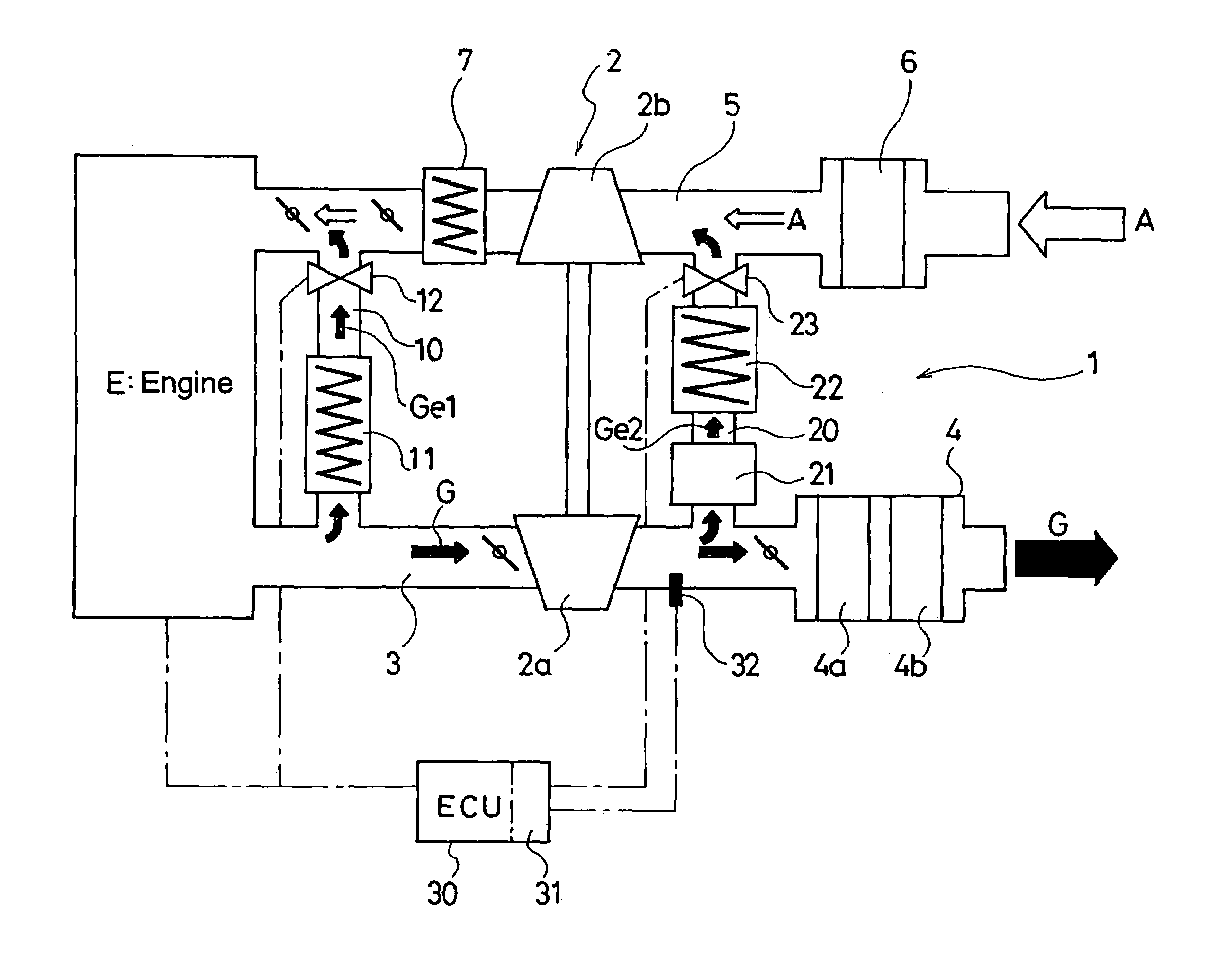
[0026]As shown in FIG. 1, in a EGR system 1 of an internal combustion engine provided with a turbo-charger in the first embodiment, an engine E is provided with a turbo-charger 2. A turbine 2a of the turbo-charger 2 is arranged in an exhaust gas passage 3 communicating with an exhaust gas manifold of the engine E, and is driven by the exhaust gas of the engine E. In the downstream side exhaust gas passage 3 of the turbine 2a, a diesel particulate filter (hereafter called DPF) 4a and an exhaust gas purifying apparatus 4 having an NOx purifying catalyst converter 4b are arranged.

[0027]The compressor 2b driven by the turbine 2a is arranged in an intake passage 5, and sucks and compresses air A coming therein via an air intake filter 6. The compressor 2b then makes the compressed air A pass through an inter-cooler 7 to send it to an intake manifold of the engine E.

[0028]Moreover, a first EGR passage 10 is arranged so as to be connected between the exhaust gas passage 3 at the upstream s...

second embodiment

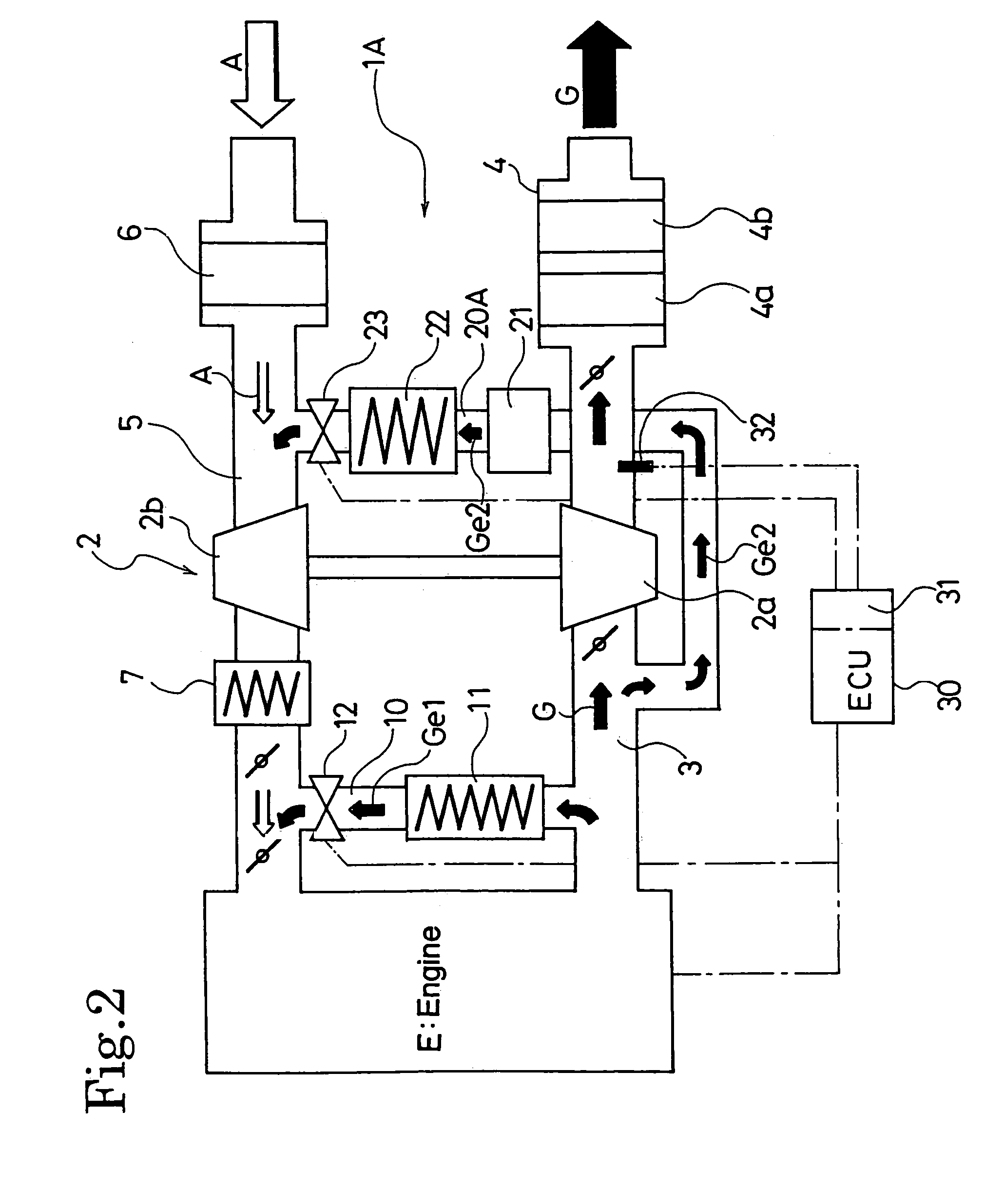
[0044]Next, an EGR system 1A for an internal combustion engine provided with a turbo-charger in the

[0045]As shown in FIG. 2, in an EGR system 1A for an internal combustion engine provided with a turbo-charger in the second embodiment, an inlet to a second EGR passage 20A is arranged at the upstream side of a turbine 2a instead of arranging it at the downstream side of the turbine 2a. This is the only point different from the EGR system 1 of the internal combustion engine provided with a turbo-charger in the first embodiment, and the other arrangements are the same.

[0046]Since this constitution has the effects similar to those of the first embodiment and EGR can be performed in a wider operation range of the engine E by using the second EGR passage 20A since higher temperature gas can be introduced into the DPF 21.

[0047]However, it is necessary to increase the cooling power of the second EGR cooler 22 because the amount of gas entering the turbine 2a decreases by the amount of the EG...


PUM


Abstract

An EGR system for an internal combustion engine provided with a first EGR passage for recirculating EGR gas to the downstream side of a compressor from the upstream side of a turbine of a turbo-charger is provided with a second EGR passage for recirculating EGR gas from the downstream side of the turbine to the upstream side of the EGR gas, and provided also with a DPF in the second EGR passage, while the exhaust gas flow in the first EGR passage and the second EGR passage is controlled based on the exhaust gas temperature detected by an exhaust gas temperature sensor arranged in the exhaust gas passage.

Description

BACKGROUND OF THE INVENTION[0001]This invention relates to an EGR system for an internal combustion engine provided with a turbo-charger, which purifies exhaust gas of the internal combustion engine such as a diesel engine.[0002]An internal combustion engine such as a diesel engine is using an EGR (exhaust gas recirculation) system for recirculating a part of the exhaust gas to an air intake passage in order to reduce emission of NOx (nitrogen oxides).[0003]According to the conventional technology, in the internal combustion engine provided with a turbo-charger, an EGR passage for performing the EGR is normally disposed by connecting the upstream side of a turbine with the downstream side of a compressor. The exhaust gas is partly branched from an inlet side of the turbine and recirculated to an outlet side of the compressor.[0004]However, the construction of the EGR passage has a problem that the EGR cannot be carried out as desired in a large type of internal combustion engine. Wh...

Claims


Application Information

Patent Timeline
IPC IPC(8): F02B33/44F01N3/02F01N3/00F02B37/00F02B29/04F02B33/00F02D9/04F02D21/08F02D23/00F02M25/07
CPCF02M25/0707F02M25/0709F02M25/071F02M25/0713F02M25/0732F02M25/074F02M25/0744F02M25/0754F02M25/0731Y02T10/121F02M26/07F02D41/029F02D41/0007F02D41/0055F02D2041/0067F02M26/05F02M26/06F02M26/10F02M26/28F02M26/24F02M26/35F02M26/38F02M26/47Y02T10/40
Inventor ISHIKAWA, NAOYA
Owner ISUZU MOTORS LTD
Why Eureka
Try Eureka