Transport Refrigeration system

a refrigeration system and transport technology, applied in the field of transport refrigeration systems, can solve the problems of electrical jumpers, electrical shock exposure of the person installing the jumpers, and loss of the desired thermal environment,

Inactive Publication Date: 2006-05-16
CARRIER CORP
View PDF23 Cites 19 Cited by
  • Summary
  • Abstract
  • Description
  • Claims
  • Application Information

AI Technical Summary

Benefits of technology

[0009]In another embodiment, the present invention includes a control module for a refrigeration system. The control module includes an electronic controller for controlling the refrigeration system and a bypass module coupled to the refrigeration system and the electronic controller. The bypass module includes a plurality of switches whereby the electronic controller may be isolated from the refrigeration system while operation of selected components of the refrigeration system is maintained.

Problems solved by technology

A particular difficulty of transporting perishable items is that such items must be maintained within a narrow temperature range to prevent, depending on the items, spoilage or conversely damage from freezing.
The failure of the electronic controller can cause loss of the desired thermal environment and the subsequent spoilage of the perishable items stored therein.
The installation of the electrical jumpers exposes the person installing the jumpers to electrical shock.

Method used


Image

  • Transport Refrigeration system
  • Transport Refrigeration system
  • Transport Refrigeration system

Examples


Embodiment Construction

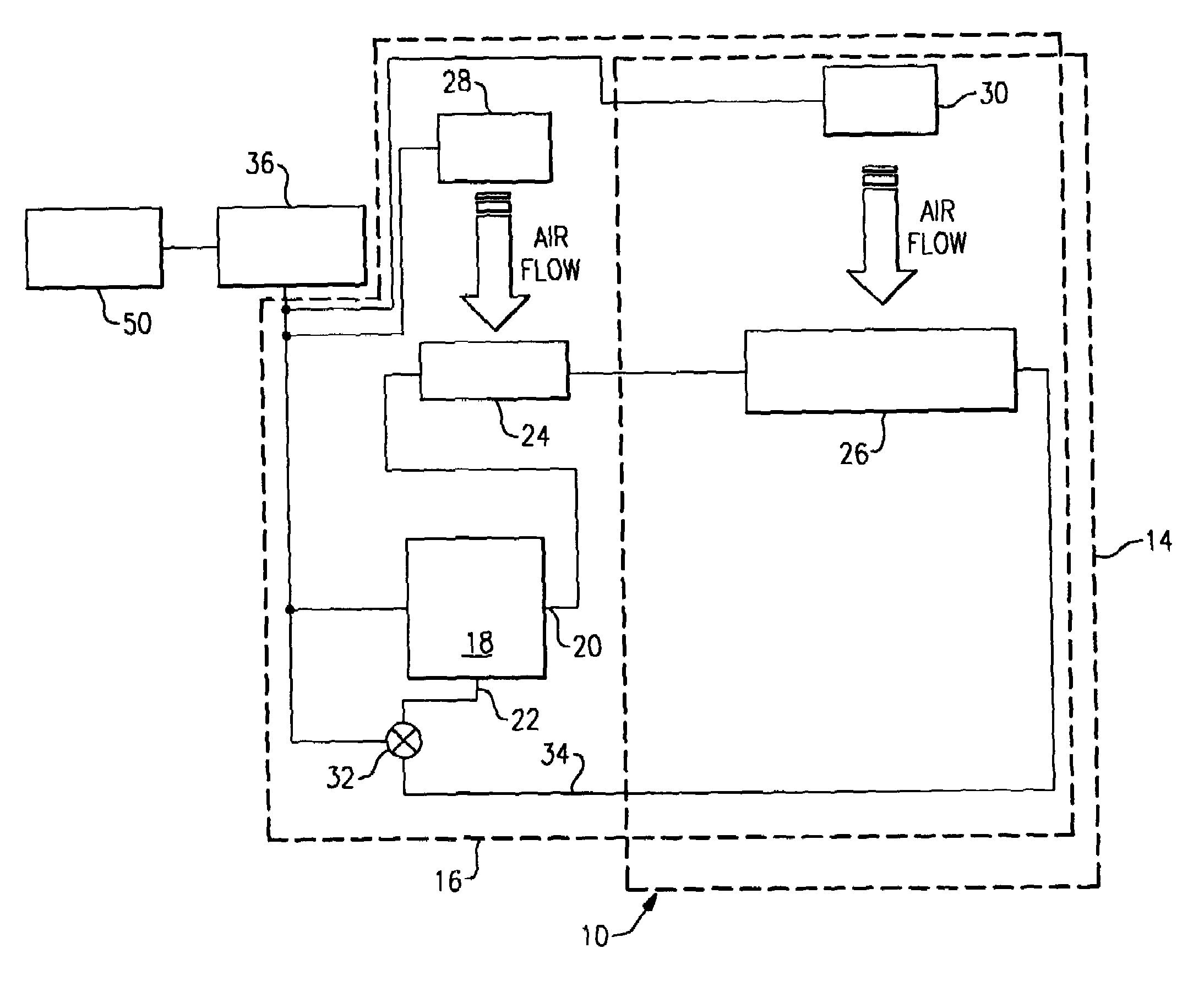
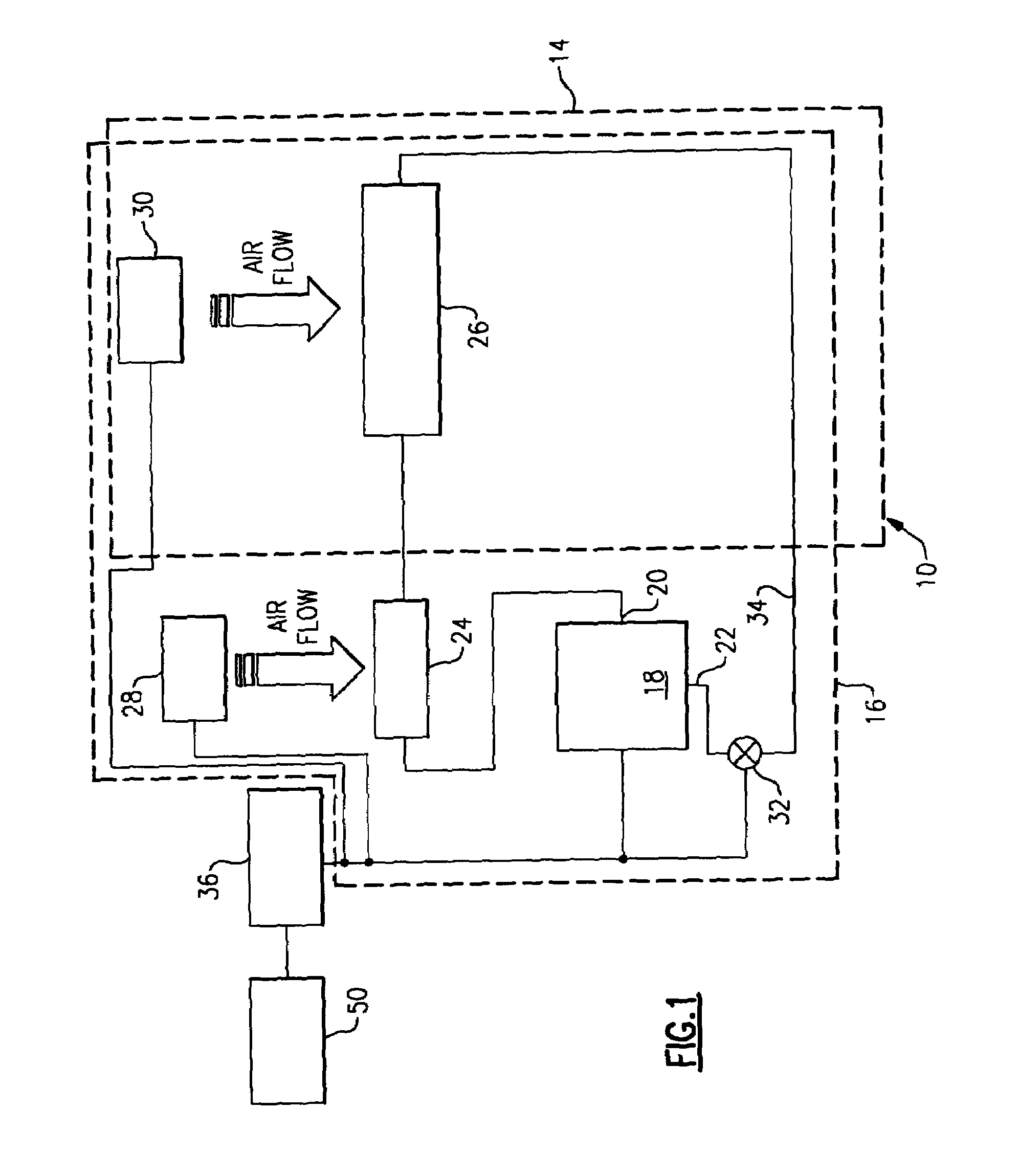
[0015]Reference will now be made in detail to the present preferred embodiments of the invention, examples of which are illustrated in the accompanying drawings. Whenever possible, the same reference numerals will be used throughout the drawings to refer to the same or like parts. An embodiment of the present invention is shown in FIG. 1, and is designated generally throughout by reference numeral 10.

[0016]FIG. 1 depicts the present invention embodied as a refrigeration unit 10 for regulating the temperature of an enclosed volume 14. The refrigeration unit 10 includes a refrigeration module 16, a bypass module 36 and an electronic controller 50. The electronic controller 50 is coupled to the bypass module 36 which is in turn coupled to the refrigeration module 16.

[0017]The refrigeration module 16 includes a compressor 18, a condenser heat exchanger 24, an evaporator heat exchanger 26, a condenser fan 28, an evaporator fan 30 and a suction modulation valve 32.

[0018]The compressor 18 ...


PUM


Abstract

A transport refrigeration system, the transport refrigeration system including a container defining an enclosed volume and a refrigeration module coupled to the container. The refrigeration module is disposed to regulate the temperature of the enclosed volume and includes a compressor having a discharge port and a suction port, a condenser heat exchanger unit operatively coupled to the discharge port, an evaporator heat exchanger unit operatively coupled to the suction port, a condenser fan disposed proximate to the condenser heat exchanger unit, an evaporator fan disposed proximate to the evaporator heat exchanger unit; and a suction modulation valve coupled to the suction port. The transport refrigeration system further includes a bypass module coupled to the refrigeration module. The bypass module includes: a bypass mode switch having a normal operation position and bypass operation position; and an operational mode switch having a full cool position and fan only position. The transport refrigeration system also includes an electronic controller coupled to the bypass module. When the bypass mode switch is in the normal operation position the electronic controller regulates the operation of the refrigeration module. When the bypass mode switch is in the bypass operation position, the compressor, the condenser fan, the evaporator fan and the suction modulation valve are selectively operated by the position of the operational mode switch.

Description

BACKGROUND OF THE INVENTION[0001]1. Field of the Invention[0002]The present invention relates to transport refrigeration systems, and more particularly to a bypass switch for transport refrigeration systems.[0003]2. Description of Related Art[0004]A particular difficulty of transporting perishable items is that such items must be maintained within a narrow temperature range to prevent, depending on the items, spoilage or conversely damage from freezing. In order to maintain proper temperatures within a transport cargo space a transport refrigeration unit is used. The transport refrigeration unit is typically under the direction of an electronic controller. The electronic controller ensures that the transport refrigeration unit maintains a certain thermal environment within a transport cargo space. The failure of the electronic controller can cause loss of the desired thermal environment and the subsequent spoilage of the perishable items stored therein. There is a need therefore for...

Claims


Application Information

Patent Timeline
Patent Type & Authority Patents(United States)
IPC IPC(8): F25B49/00F25B49/02F25D29/00
CPCF25D29/003F25B49/02F25B49/005F25B1/00F25B49/00F25D29/00
Inventor BURCHILL, JEFFREY JOHNPLETL, JOHN
Owner CARRIER CORP
Why Eureka
Try Eureka