Tool calibrator and tracker system

Inactive Publication Date: 2006-05-16
MAKO SURGICAL CORP
View PDF19 Cites 318 Cited by
  • Summary
  • Abstract
  • Description
  • Claims
  • Application Information

AI Technical Summary

Benefits of technology

[0010]In order to simplify and/or make more accurate the process of calibrating a standard medical or surgical tool for use in an image guided interventional system, a standard medical or surgical tool's axis is located by attaching to the tool a plurality location indicating elements or markers having a known geometric relationship, and placing the tool in a tool calibrator that supports the tool in a manner that allows tools of different diameters to be rotated while maintaining the tool's axis in a fixed or stable orientation. As the tool is rotated, a marker locating system tracks the positions of the markers on the tool and then extr

Problems solved by technology

Unfortunately, because the position of the tip of each tool with respect to the tool's position indicating elements and the tool head diameter in conventional systems are preprogrammed changes to the tool which affect the location of the tip

Method used


Image

  • Tool calibrator and tracker system
  • Tool calibrator and tracker system
  • Tool calibrator and tracker system

Examples


Example

DETAILED DESCRIPTION OF THE DRAWINGS

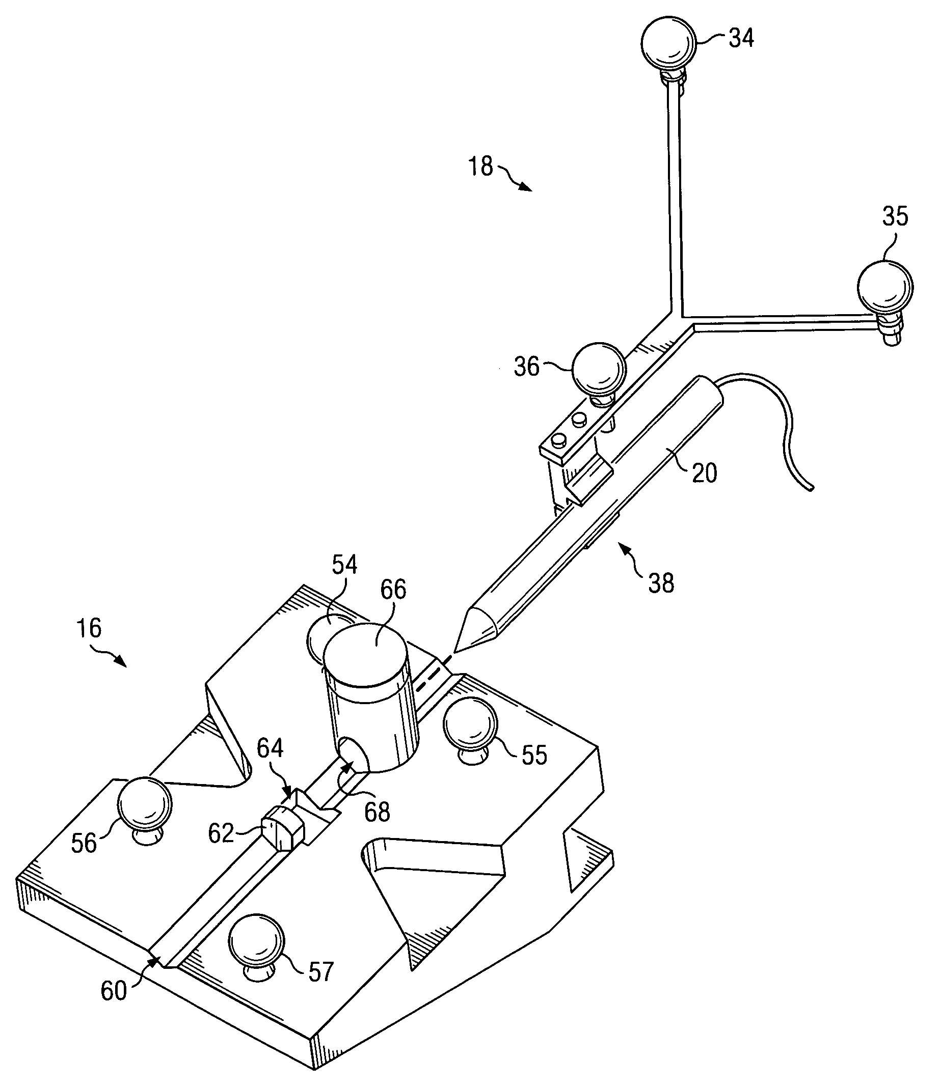
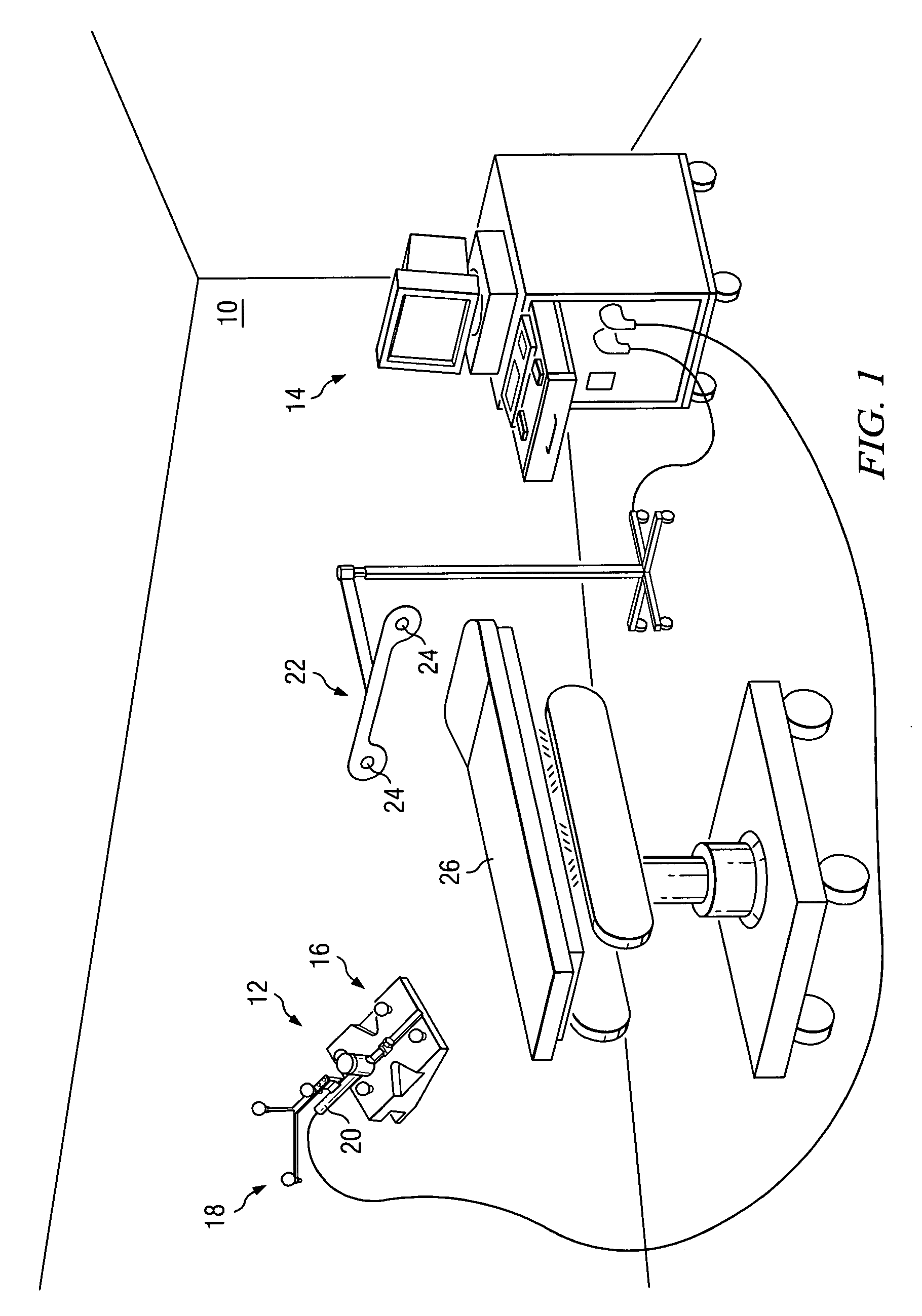
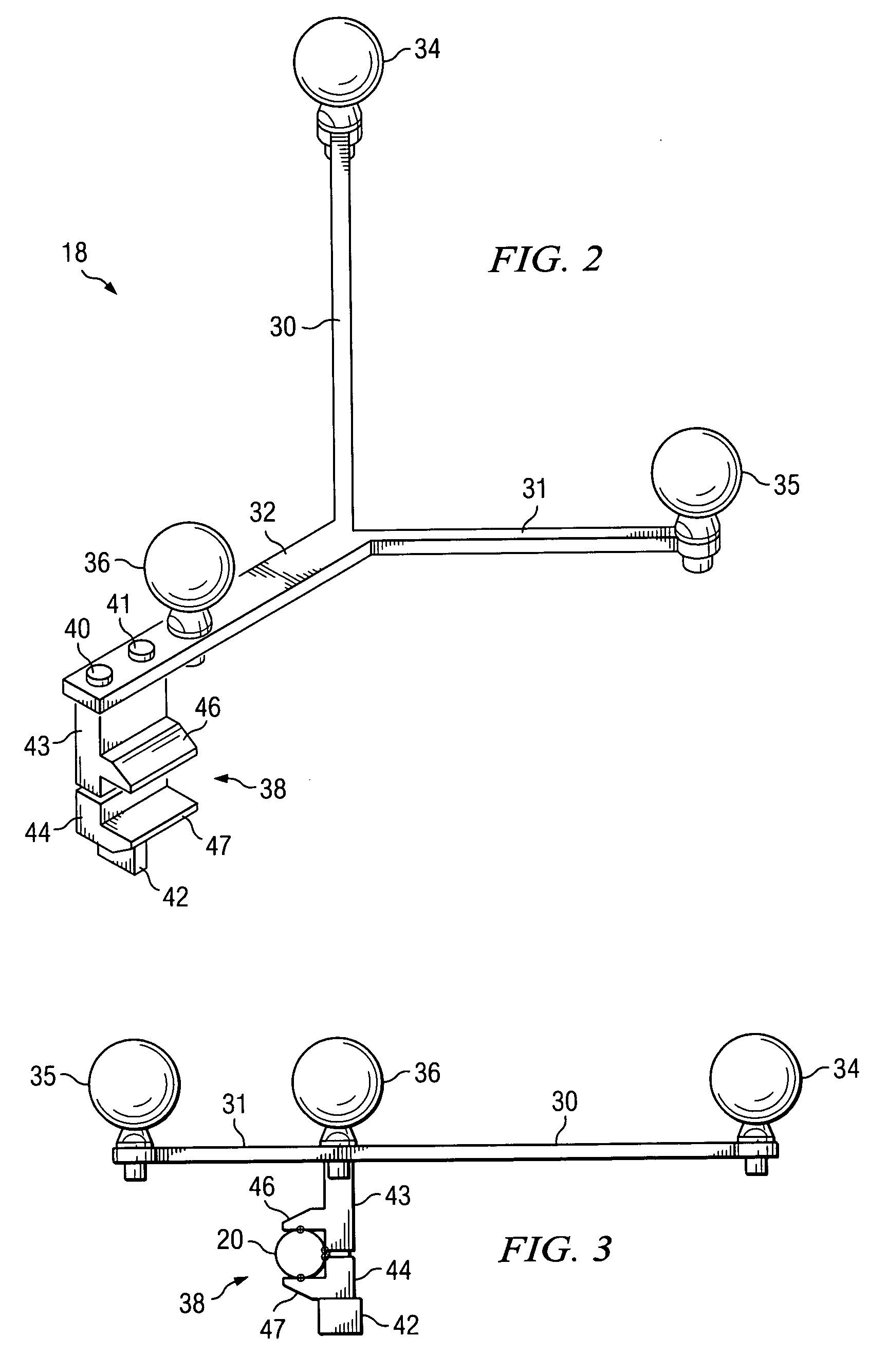
[0018]FIG. 1 is a perspective view of an operating room 10 in which a tool calibrator and tracker system 12 is deployed and used with an image guided surgery system 14. Tool calibrator and tracker system 12 includes a tool calibrator 16 and a tool tracker 18. Tool tracker 18 is attachable to a tool 20, such as a medical probe, drill or endoscopes. Tool 20 is operable to be installed in tool calibrator 16 to register the tool to the image guided system. A locating system 22 is mounted in a known position relative to an table 26 upon which a patient will be supported. Locating system 22 may be mounted in another manner with respect to another suitable known location in operating room 10. The locating system included, in the illustrative embodiment, is a passive infrared optical system that includes two cameras 24 on an infrared radiation source that illuminates the viewing area of the cameras with infrared radiation. Such systems are well known. How...


PUM


Abstract

A standard medical or surgical tool's axis is located by attaching to the tool a plurality of a location indicating elements or markers having a known geometric or spatial relationship, and placing the tool in a tool calibrator that supports the tool in a manner that allows tools of different diameters to be rotated while maintaining the tool's axis in a fixed or stable orientation. As the tool is rotated, a marker locating system tracks the positions of the markers on the tool and then extrapolates or determines the axis of rotation with respect to the markers clamped to the tool. The tool calibrator has a second set of position indicating elements or markers with fixed geometric or spatial relationship with one another and with respect to a stop, against which the end or tip of the tool is placed.

Description

RELATED APPLICATION[0001]This application claims priority to U.S. Provisional Application No. 60 / 265,483 filed Jan. 30, 2001 entitled, “Tool Calibrator and Tracker System”.TECHNICAL FIELD OF THE INVENTION[0002]This invention relates generally to a tool calibrator for a medical tool tracking system.BACKGROUND OF THE INVENTION[0003]Three-dimensional diagnostic images of the brain, spinal cord, and other body portions can be produced by diagnostic imaging equipment such as CT scanners, magnetic resonance imagers, three-dimensional fluoroscopes, and the like. These imaging modalities often provide structural detail with a resolution of a millimeter or better. Image guided interventional systems have been developed to utilize this data to assist a doctor, surgeon or other specialist in connection with planning of an medical, surgical or other type of interventional procedure and in accurately locating a region of interest within the body of a patient during the procedure.[0004]Image guid...

Claims


Application Information

Patent Timeline
IPC IPC(8): G01B3/30A61B1/00A61B17/00A61B19/00
CPCA61B19/52A61B19/5244A61B2017/00725A61B2019/5483A61B2019/5255A61B2019/527A61B2019/507A61B34/20A61B90/36A61B2034/107A61B2034/2055A61B2034/207A61B2090/3983
Inventor PANDEY, RAJESHARATA, LOUISLAROCQUE, BRANDON
Owner MAKO SURGICAL CORP
Why Eureka
Try Eureka