Laser processing method and laser beam processing machine

Active Publication Date: 2008-03-13
DISCO CORP
View PDF7 Cites 3 Cited by
  • Summary
  • Abstract
  • Description
  • Claims
  • Application Information

AI Technical Summary

Benefits of technology

[0013]In the laser processing method and the laser beam processing machine according to the present invention, when the linear portions of the processing lines are located at the application position of a laser beam, the focal spot changing means is activated to make an elliptic focal spot and the long axis of the elliptic focal spot is positioned along the linear portions of the processing lines and when the cu

Problems solved by technology

When the optical device wafer is cut with the cutting machine, cutting chips adhere to the front surface of an optical device to decrease the quality of the optical device.
However, when the focal spot shape of the laser beam is elliptic, it is difficult to position the long axis of the elliptic focal spot along the processing lines even by controlling the above process

Method used


Image

  • Laser processing method and laser beam processing machine
  • Laser processing method and laser beam processing machine
  • Laser processing method and laser beam processing machine

Examples


Example

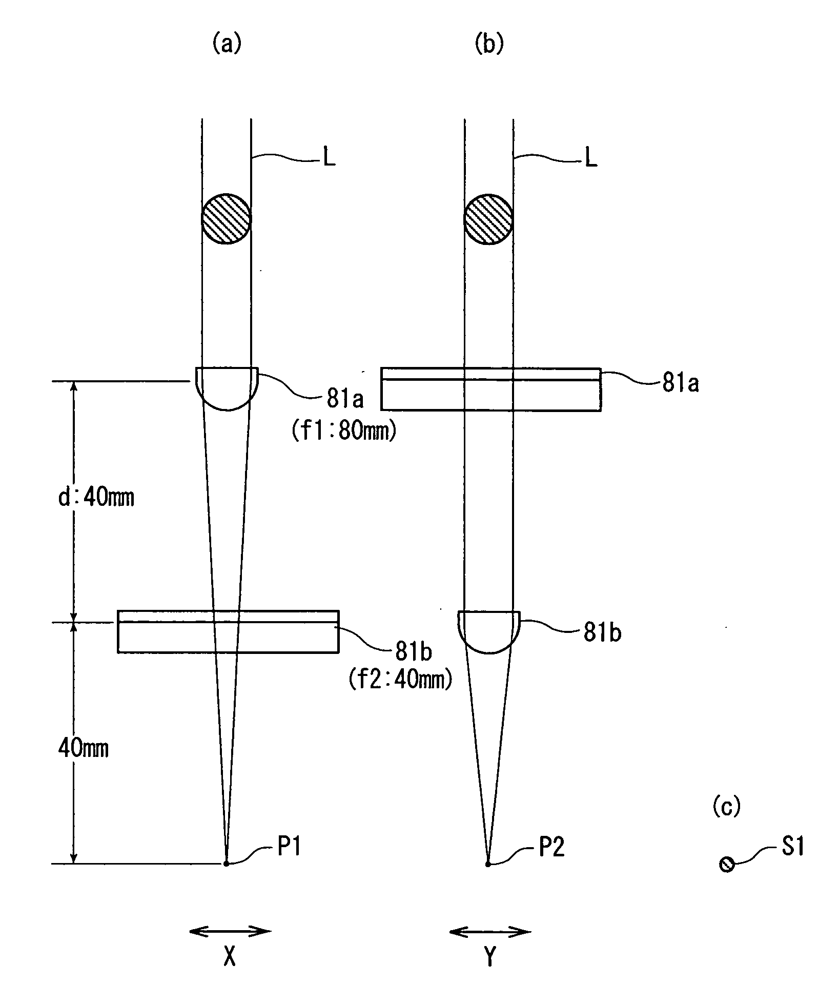
[0028]The laser processing method and the laser beam processing machine according to the present invention will be described in more detail with reference to the accompanying drawings.

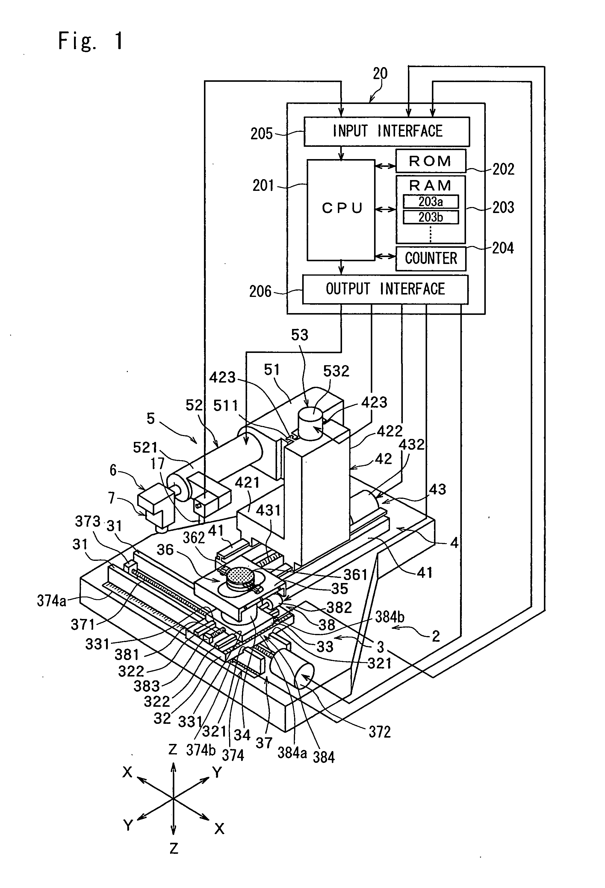
[0029]FIG. 1 is a perspective view of a laser beam processing machine constituted according to the present invention. The laser beam processing machine 1 shown in FIG. 1 comprises a stationary base 2, a chuck table mechanism 3 for holding a workpiece, which is mounted on the stationary base 2 in such a manner that it can move in a processing feed direction (X direction) indicated by an arrow X, a laser beam application unit support mechanism 4 mounted on the stationary base 2 in such a manner that it can move in an indexing-feed direction (Y direction) indicated by an arrow Y perpendicular to the direction (X direction) indicated by the arrow X, and a laser beam application unit 5 mounted to the laser beam application unit support mechanism 4 in such a manner that it can move in a direction (Z directio...


PUM


Abstract

A method of carrying out laser processing along processing lines having linear portions and curved portions formed on a workpiece by using a laser beam processing machine comprising a laser beam application means for applying a laser beam to the workpiece held on a chuck table which comprises a condenser for converging a laser beam, having a focal spot changing means for changing the shape of a focal spot between an elliptic spot and a circular spot, comprising the steps of:
    • moving a processing line formed on the workpiece to the application position of a laser beam, activating the focal spot changing means to make an elliptic focal spot and positioning the long axis of the elliptic spot along a linear portion of the processing line when the linear portion of the processing line is located at the application position of the laser beam and activating the focal spot changing means to make a circular focal spot when a curved portion of the processing line is located at the application position of the laser beam.

Description

FIELD OF THE INVENTION[0001]The present invention relates to a method of carrying out laser processing along processing lines having linear portions and curved portions formed on a workpiece and to a laser beam processing machine.DESCRIPTION OF THE PRIOR ART[0002]In the process of manufacturing an optical device such as CCD, a plurality of areas are sectioned by dividing lines called “streets” arranged in a lattice on the front surface of an optical device wafer, and an optical device such as CCD and the like is formed in each of the sectioned areas. Individual optical devices are manufactured by cutting this optical device wafer along the streets to divide it into the device formed areas.[0003]Cutting along the streets of the optical device wafer is generally carried out by using a cutting machine. When the optical device wafer is cut with the cutting machine, cutting chips adhere to the front surface of an optical device to decrease the quality of the optical device.[0004]Meanwhil...

Claims


Application Information

Patent Timeline
IPC IPC(8): B23K26/06B23K26/02B23K26/073B23K101/40H01L21/301
CPCB23K26/0853B23K26/0736
Inventor MURATA, MSAHIROMORIKAZU, HIROSHI
Owner DISCO CORP
Why Eureka
Try Eureka