Laser scanning microscope

Active Publication Date: 2008-11-13
EVIDENT CORP
View PDF7 Cites 6 Cited by
  • Summary
  • Abstract
  • Description
  • Claims
  • Application Information

AI Technical Summary

Benefits of technology

[0008]The present invention provides a laser microscope that can obtain fluorescence images whose positional shifts between pixels of different fluorescence images obtained through ir

Problems solved by technology

Consequently, unmixing processing of such a plurality of fluorescence images whose pixels are positionally shifted from each other results in a meaningless process be

Method used


Image

  • Laser scanning microscope
  • Laser scanning microscope
  • Laser scanning microscope

Examples


Example

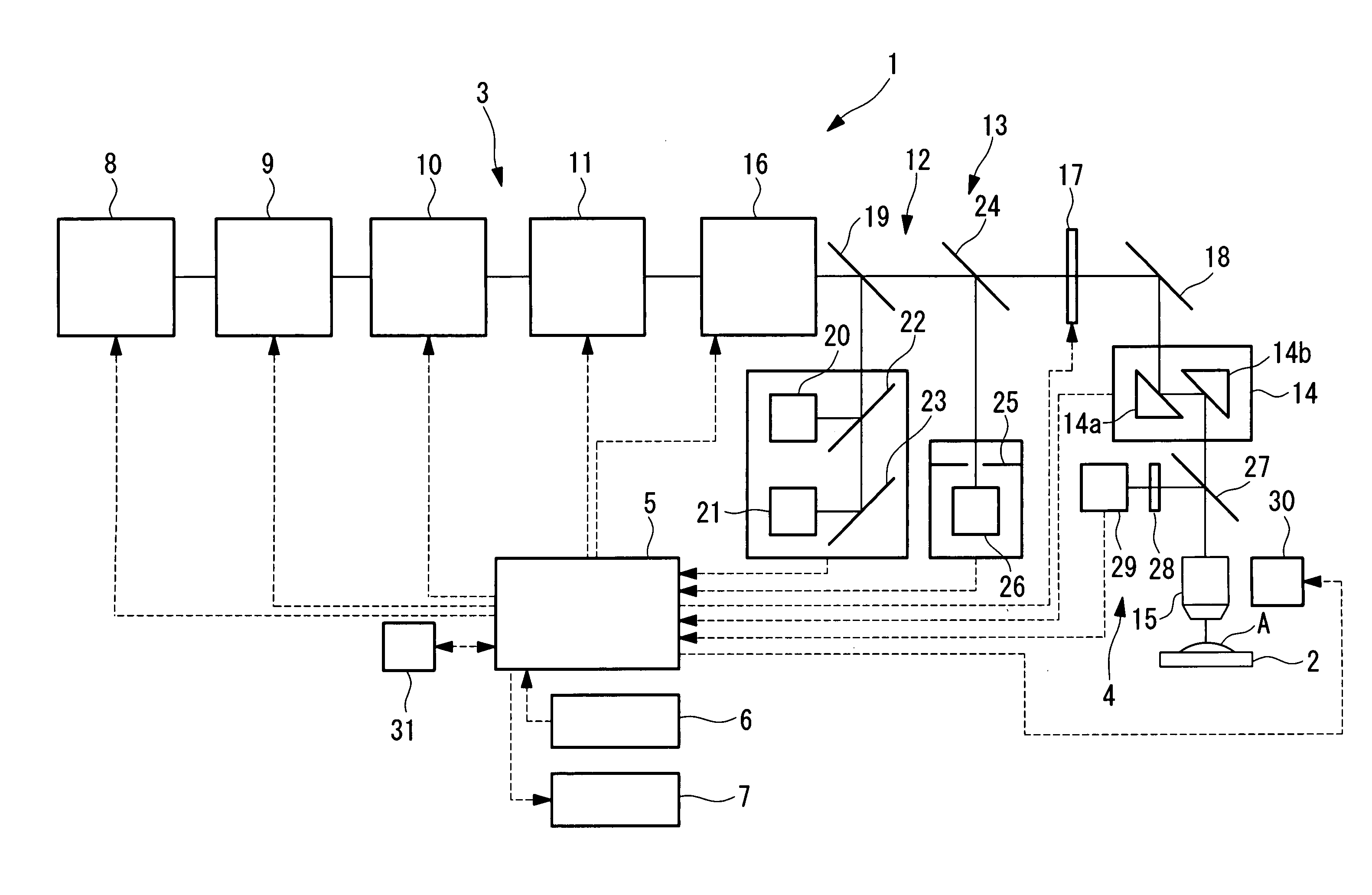
[0030]A laser scanning microscope 1 according to an embodiment of the present invention will now be described with reference to FIGS. 1 to 3.

[0031]Referring to FIG. 1, the laser scanning microscope 1 according to the embodiment includes the following: an illumination optical system 3 that irradiates an ultrashort-pulse laser light (hereinafter referred to as a laser light) to a specimen A placed on a stage 2, an observation optical system 4 that detects fluorescence emitted from the specimen A, a control device 5 that controls the illumination optical system 3 and the observation optical system 4, an input device 6 for inputting various settings, and a display device 7 that displays an obtained fluorescence image.

[0032]The illumination optical system 3 includes the following: a laser light source 8 that can emit a multi-wavelength laser light; an acoustooptic element (light modulating unit) 9, such as an acoustooptic tunable filter (AOTF), that turns the laser light emitted from the...


PUM


Abstract

A laser scanning microscope is capable of separating the fluorescence signals of different fluorophores in accurate unmixing realized by eliminating positional pixels shifts between different fluorescence images obtained through irradiation of different-wavelength laser lights. The microscope includes a laser light source capable of emitting a wavelength-changeable laser light, a correction amount determination unit that determines a correction amount for correcting an optical axis shift of the laser light, an optical axis adjusting unit that adjusts an optical axis, a scanning unit that performs two-dimensional scanning, an objective lens that focuses the laser scanning light to a specimen and fluorescence emitted from the specimen, a light detector that detects the fluorescence, and a control unit that changes the wavelength of the laser light synchronously with the scanning by the scanning unit while controlling the optical axis adjusting unit on the basis of the correction amount determined by correction amount determination unit.

Description

BACKGROUND OF THE INVENTION[0001]1. Field of the Invention[0002]The present invention relates to laser scanning microscopes.[0003]This application is based on Japanese Patent Application No. 2007-037832, the content of which is incorporated herein by reference.[0004]2. Description of Related Art[0005]There is a known technique for separating some different fluorescence each of whose wavelength components are overlapping each other, by unmixing processing a set of images obtained through use of a laser light source whose wavelength is changeable, such as a pulsed laser light source (see Japanese Unexamined Patent Application, Publication No. 2004-233351, for example).[0006]In the known technique disclosed in Japanese Unexamined Patent Application, Publication No. 2004-233351, however, since a pulsed laser light source whose wavelength is changeable is used, the optical axis of the optical path running from the laser light source to the specimen may be shifted when the wavelength of t...

Claims


Application Information

Patent Timeline
IPC IPC(8): G02B21/06
CPCG02B21/0076G02B21/16
Inventor KOIKE, TETSUYAHATTORI, TOSHIYUKI
Owner EVIDENT CORP
Why Eureka
Try Eureka