Data regenerating apparatus

Inactive Publication Date: 2006-04-18
FUJITSU LTD
View PDF4 Cites 3 Cited by
  • Summary
  • Abstract
  • Description
  • Claims
  • Application Information

AI Technical Summary

Benefits of technology

[0031]The object of the present invention is to provide a data regenerating apparatus that enables an accura

Problems solved by technology

However, increasing the number of iterations of the decoding process will lead to an increase in the time requ

Method used


Image

  • Data regenerating apparatus
  • Data regenerating apparatus
  • Data regenerating apparatus

Examples


Example

[0068]In the following, a description of the preferred embodiments of the present invention is given with reference to the accompanying drawings.

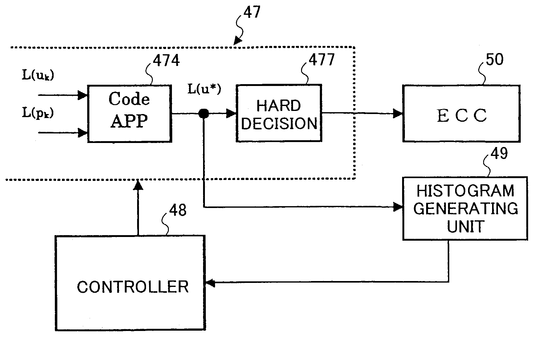
[0069]A data regenerating apparatus according to an embodiment of the present invention may have, for example, a structure as shown in FIG. 4. In FIG. 4, the data regenerating apparatus is implemented as the read system of the data recording / regenerating apparatus, which performs the recording and regeneration of data.

[0070]The data recording / regenerating apparatus shown in FIG. 4 is an optical disk unit using a magneto-optic disk (MO) 110 as the storage medium, comprising a recording / regenerating mechanism 100, a write system for writing data onto a magneto-optic disk 110, and a read system for regenerating data from the magneto-optic disk 110. The above recording / regenerating mechanism 100 has an optical head (not shown) provided with a light beam output unit (e.g. laser diode (LD)), a light detector (e.g. photodiode), and a disk drive 12...


PUM


Abstract

A data regenerating apparatus that generates decoded data by performing a decoding process on a readout signal from a storage medium according to an iterative decoding technique corresponding to a turbo coding technique, and regenerates recorded data by performing a predetermined error correction process on the decoded data is disclosed. The apparatus includes an error state detector configured to detect an error state of the decoded data; a first determination unit configured to determine whether or not the error state of the decoded data detected by the error state detector is correctable in the predetermined error correction process; and, a decoding controller configured to stop the decoding process when it is determined by the first determination unit that the error state of the decoded data is correctable in the predetermined error correction process.

Description

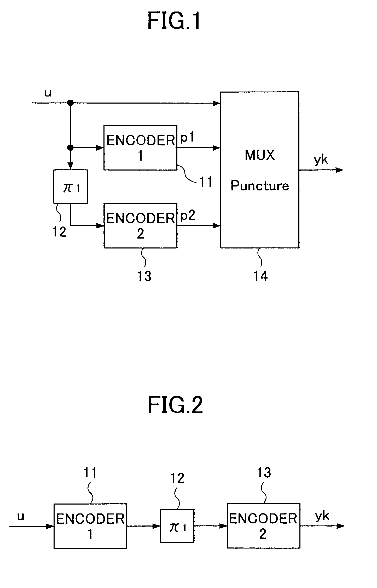
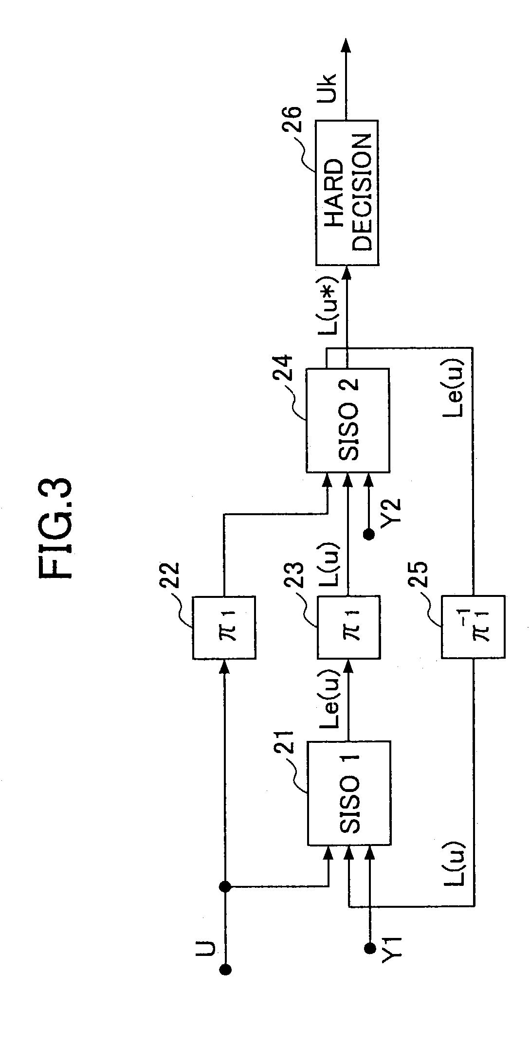
BACKGROUND OF THE INVENTION[0001]1. Field of the Invention[0002]The present invention relates generally to a data regenerating apparatus such as a magnetic disk unit, an optical disk unit, or a magnetic tape unit, and particularly to a data regenerating apparatus that regenerates recorded data from a storage medium using an iterative decoding technique corresponding to a turbo coding technique.[0003]2. Description of the Related Art[0004]Turbo coding is an encoding technique with a large coding gain, and this technique has attracted much attention in the communications field. A turbo coding device generally encodes a data bit sequence u with two recursive systematic convolutional encoders, and may be arranged into a structure as shown in FIG. 1 or 2.[0005]In FIG. 1, the turbo coding device comprises a first encoder 11, an interleaver (π1) 12, a second encoder 13, and a synthesizer 14. The data bit sequence u is supplied to the first encoder 11 as well as to the second encoder 13 via...

Claims


Application Information

Patent Timeline
IPC IPC(8): H03M13/03G11B20/10G11B20/18H03M13/29
CPCH03M13/2957H03M13/6362H03M13/6343H03M13/2975
Inventor ITAKURA, AKIHIRO
Owner FUJITSU LTD
Why Eureka
Try Eureka