Variable inertia flywheel apparatus

a technology of variable inertia and flywheel, which is applied in the direction of cranks, mechanical control devices, instruments, etc., can solve the problems of inadequate compromise of acceleration characteristics of engines and engine torque stabilization, engine torque deterioration, and engine torque may become unstable, so as to achieve the effect of efficient varying the inertia of rotational momentum

Inactive Publication Date: 2006-05-16
HYUNDAI MOTOR CO LTD
View PDF5 Cites 26 Cited by
  • Summary
  • Abstract
  • Description
  • Claims
  • Application Information

AI Technical Summary

Benefits of technology

[0007]Embodiments of the present invention provide a variable inertia flywheel apparatus having non-limiting advantages of efficiently varying its rotational momentum inertia.

Problems solved by technology

When a mass of the flywheel is increased, acceleration characteristics of the engine deteriorate.
To the contrary, when the mass of the flywheel is reduced, the engine torque may become unstable.
In this respect, the rotational inertia of a flywheel is designed such that acceleration characteristics of an engine and stabilization of engine torque are appropriately compromised.

Method used


Image

  • Variable inertia flywheel apparatus
  • Variable inertia flywheel apparatus
  • Variable inertia flywheel apparatus

Examples


Embodiment Construction

[0021]An embodiment of the present invention will hereinafter be described in detail with reference to the accompanying drawings.

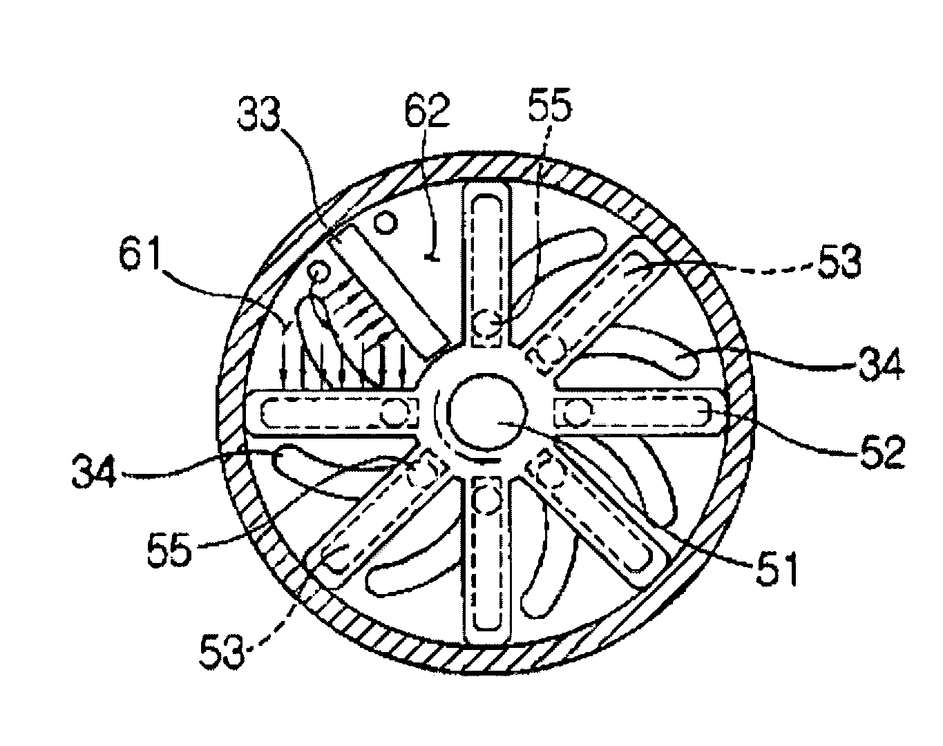
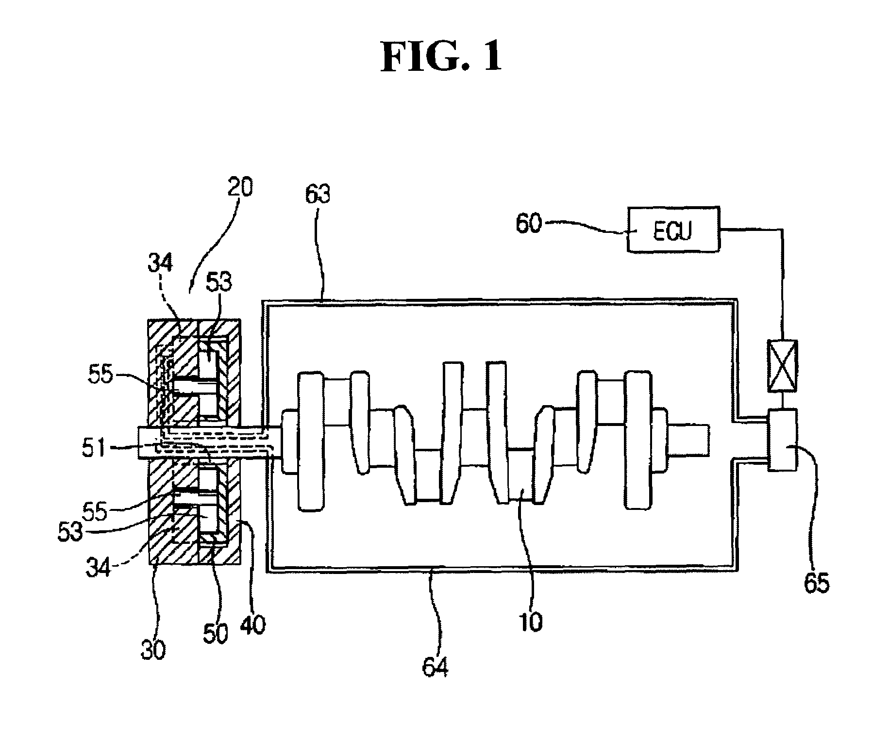
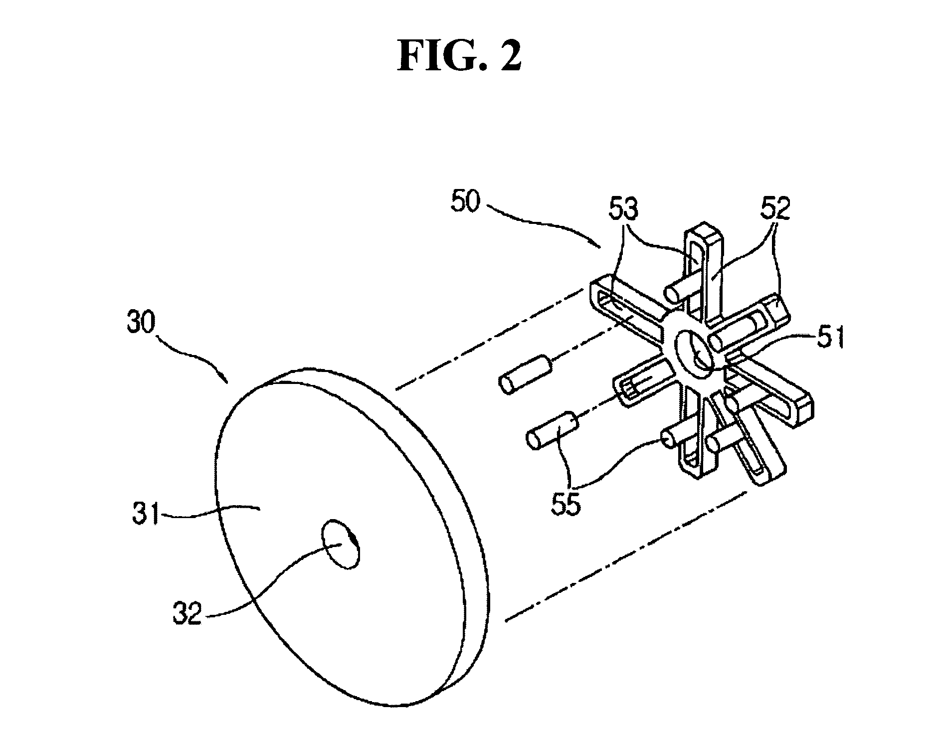
[0022]Reference number 20 in the drawings indicates a variable inertia flywheel according to an embodiment of the present invention, and reference number 10 indicates a crankshaft for mounting the variable inertia flywheel 20 according to an embodiment of the present invention. The flywheel 20 is fixed to an end of the crankshaft 10, and includes a body 30, a cover 40, and a rotatable member 50.

[0023]The body 30 has a circular plate 31 of a predetermined size. The body 30 has a shaft-receiving hole 32 at its center, and an end of the crankshaft 10 is inserted into the shaft-receiving hole 32. In addition, a wall 33 (FIG. 3) is projected on an interior side of the body 30. The wall 33 is aligned in a radial direction of the body 30. When the body 30 is assembled with the rotatable member 50, the wall 33 divides one of chambers formed by rails 52 of the rota...


PUM


Abstract

In a flywheel having variable inertia, first and second guide grooves are respectively formed at a body and a rotatable member such that an overlapping position thereof is varied according to a relative rotation thereof. A movable mass is disposed at the overlapping position, and the rotatable member rotates relatively to the body by hydraulic pressure.

Description

CROSS-REFERENCE TO RELATED APPLICATIONS[0001]This application claims priority of Korean Application No. 10-2003-0063072, filed on Sep. 9, 2003, the disclosure of which is incorporated fully herein by reference.FIELD OF THE INVENTION[0002]Generally, the present invention relates to a variable inertia flywheel apparatus. More particularly, the present invention relates to a variable inertia flywheel apparatus for enhancement of the performance and fuel consumption characteristics of an engine by varying a rotational inertia of the flywheel during operation of the engine.BACKGROUND OF THE INVENTION[0003]An internal combustion engine produces power by converting combustion pressure formed in a cylinder to rotational torque of a crankshaft. The combustion pressure in the cylinder is time variant depending on crank angle. That is, an output torque of the crankshaft (i.e., engine torque) is not constant and it fluctuates depending on the crank angle. Therefore, in order to prevent unstable...

Claims


Application Information

Patent Timeline
Patent Type & Authority Patents(United States)
IPC IPC(8): F16F15/14F16C15/00F16F15/30F16F15/31G05G1/00
CPCF16F15/31Y10T74/2121Y10T74/2111Y10T74/2128Y10T74/2123Y10T74/2115F16F15/30
Inventor KIM, TAE IK
Owner HYUNDAI MOTOR CO LTD
Why Eureka
Try Eureka